Multiple slot switch

A switch and multi-slot technology, applied in the field of data communication, can solve the problems of fewer ports, fewer slots, and increased message forwarding delay, etc., to achieve the effect of reducing signal attenuation and increasing slots

Active Publication Date: 2012-06-13
RUIJIE NETWORKS CO LTD
View PDF5 Cites 6 Cited by
  • Summary
  • Abstract
  • Description
  • Claims
  • Application Information

AI Technical Summary

Problems solved by technology

[0006] In order to increase the slot positions of the switch, the prior art proposes a cluster technology, which integrates the two chassis through the cluster technology, and currently includes the following two solutions: 1) as Figure 5a As shown in the figure, the cluster management is realized through the interface cards, that is, the user ports of some of the interface cards are connected through external cables as dedicated cluster channels. The number of interconnected ports between each chassis is generally relatively small, so it is difficult to achieve wire-speed switching of all user ports across chassis, and the packet forwarding from the user port of one chassis to the user port of another chassis needs to pass through the cluster port, which increases the delay of message forwarding; 2) if Figure 5b As shown, the cluster management is implemented through the

Method used


Image

  • Multiple slot switch
  • Multiple slot switch
  • Multiple slot switch

Examples


Example Embodiment

[0036] In order to increase the number of actual available slots of the switch in the same chassis and reduce the attenuation of high-speed signals, an embodiment of the present invention provides a multi-slot switch.

[0037] The preferred embodiments of the present invention will be described below in conjunction with the accompanying drawings of the specification. It should be understood that the preferred embodiments described here are only used to illustrate and explain the present invention, not to limit the present invention, and in the case of no conflict, the present invention The embodiments in and the features in the embodiments can be combined with each other.

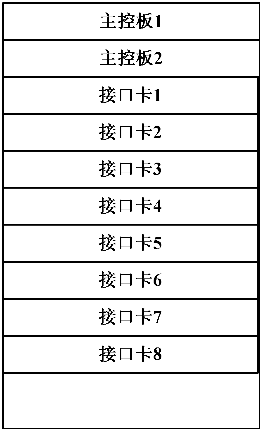
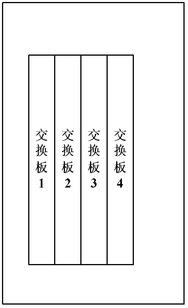
[0038] Such as Figure 6a , Figure 6b with Figure 6c Shown are the front view, side view and back view of the multi-slot switch provided by the embodiments of the present invention, including a backplane, at least one main control board and two switching sub-units, each switching sub-unit includes multiple inte...


PUM


Abstract

The invention discloses a multiple slot switch used for increasing the actual available slot number of the switch in a same cabinet and reducing high speed signal attenuation simultaneously. The multiple slot switch comprises a backboard, at least a main control board and two switch subunits. Each switch subunit comprises a plurality of interface cards, at least a first order switch board and at least a second order switch board. The main control board is connected with each interface card, the first order switch board and the second order switch board of the two switch subunits respectively and is used for managing the interface cards, the first order switch board and the second order switch board. To any switch subunit, any first order switch board in the switch subunit is in quadrature connection with any interface card and any second order switch board in the present switch subunit through a first socket connector which is fixed on the backboard. Between the switch subunits, each first order switch board of the switch subunit is connected with each second order switch board in the other switch subunit.

Description

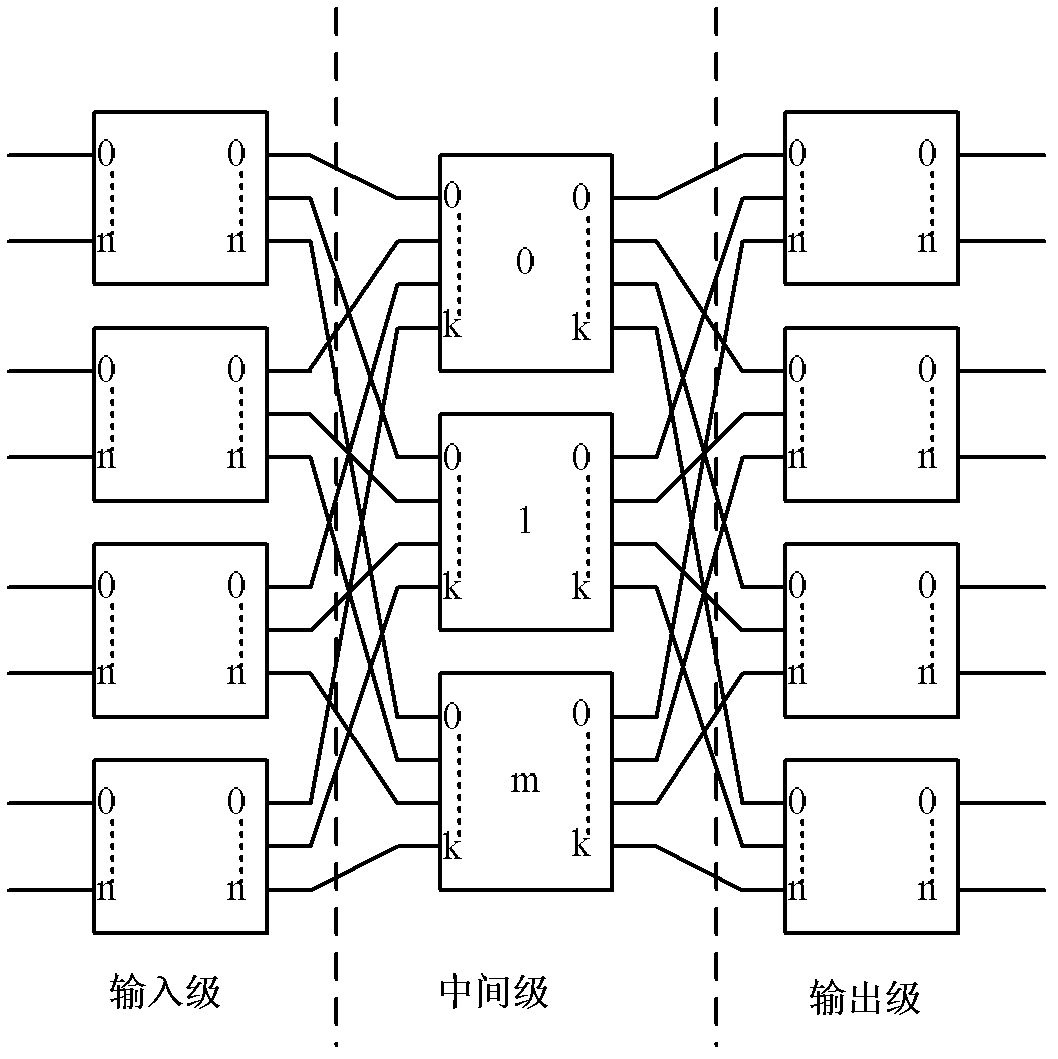
technical field [0001] The invention relates to the technical field of data communication, in particular to a multi-slot switch. Background technique [0002] The switches in the data center need to face the characteristics of high load, large bursts, and complex traffic models in the data center. In addition, they also need to face the increasingly strong trend of switching, storage, and computing. Therefore, the switches in the data center are generally Adopt strictly non-blocking CLOS switching architecture. [0003] The CLOS switching idea was proposed by Charles CLOS in his article "A Study of Nonblocking Switching Networks" in 1953, so it is named after it. The CLOS switching structure based on the CLOS switching idea is a multi-level multi-path structure, and the purpose is to reduce cross nodes while realizing non-blocking switching. At present, the most used is the 3-level CLOS switching structure, such as figure 1 As shown, it is a brief block diagram based on C...

Claims


Application Information

Patent Timeline
IPC IPC(8): H04L12/56H04L12/933
Inventor 黄金思
Owner RUIJIE NETWORKS CO LTD
Why Eureka
Try Eureka