Crack double-waveguide antenna

A double waveguide and slit technology, applied in leaky waveguide antennas, antennas, antenna coupling, etc., can solve the problems of large signal attenuation, poor anti-interference ability, poor anti-interference performance, etc., and achieve the effect of small signal attenuation and saving space resources

Active Publication Date: 2016-10-05
中电科微波通信(上海)股份有限公司
View PDF6 Cites 6 Cited by
  • Summary
  • Abstract
  • Description
  • Claims
  • Application Information

AI Technical Summary

Problems solved by technology

The free wireless method directly uses free space to transmit signals. Therefore, the signal attenuation of this transmission method is relatively large, and it is very susceptible to interference from external signals.
As the electromagnetic environment becomes more and more complex, the anti-interference ability becomes worse and worse
In this way, the current MIMO technology also has shortcomings such as large signal attenuation and poor anti-interference performance.

Method used


Image

  • Crack double-waveguide antenna
  • Crack double-waveguide antenna
  • Crack double-waveguide antenna

Examples


Embodiment 1

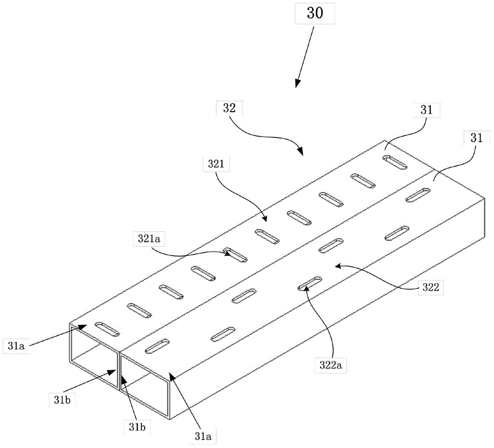
[0022] figure 1 It is a structural schematic diagram of the slotted dual-waveguide antenna in Embodiment 1 of the present invention.

[0023] like figure 1 As shown, in the first embodiment, the slotted dual-waveguide antenna 30 is used to transmit and radiate electromagnetic wave signals of different frequencies. The slotted dual-waveguide antenna 30 includes: two waveguides 31 and a slot group 32 .

[0024] In the first embodiment, the structures of the two waveguides 31 are completely the same, and only one of the waveguides 31 will be described in detail here, and the detailed description of the other waveguide 31 will be omitted.

[0025] The waveguide 31 is in the shape of a rectangular tube with an air structure inside and is used for transmitting electromagnetic wave signals. The waveguide 31 has two broad sides 31a and two narrow sides 31b.

[0026] The two waveguides 31 are fixedly connected by two narrow sides 31b, such as figure 1 As shown, the lower narrow si...

Embodiment 2

[0038] In the second embodiment, the same structures as those in the first embodiment use the same symbols, and the same descriptions are omitted.

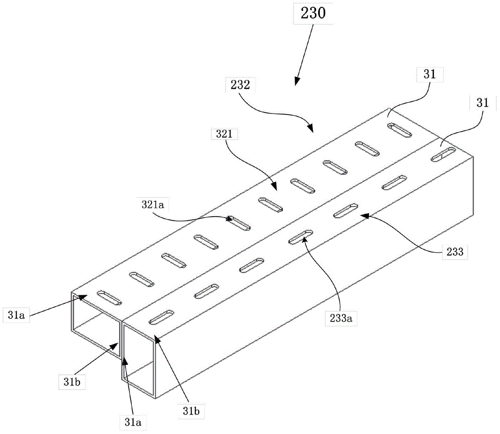
[0039] figure 2 It is a structural schematic diagram of the slotted dual-waveguide antenna in Embodiment 2 of the present invention.

[0040] like figure 2 As shown, in the second embodiment, the slotted dual-waveguide antenna 230 includes: two waveguides 31 and a slot group 232 .

[0041] The two slotted waveguides 31 are fixedly connected by the narrow side 31b of one waveguide 31 and the wide side 31a of the other waveguide 31 . like figure 2 As shown, the lower narrow side 31 b of the upper waveguide 31 is fixedly connected to the upper wide side 31 a of the lower waveguide 31 .

[0042] The slit group 232 is provided on the adjacent broad side 31 a and narrow side 31 b of the two waveguides 31 . The fracture group 232 includes a first fracture group 321 and a second fracture group 233 .

[0043] The first slit group ...

Embodiment 3

[0051] In the third embodiment, the same structures as those in the first embodiment use the same symbols, and the same descriptions are omitted.

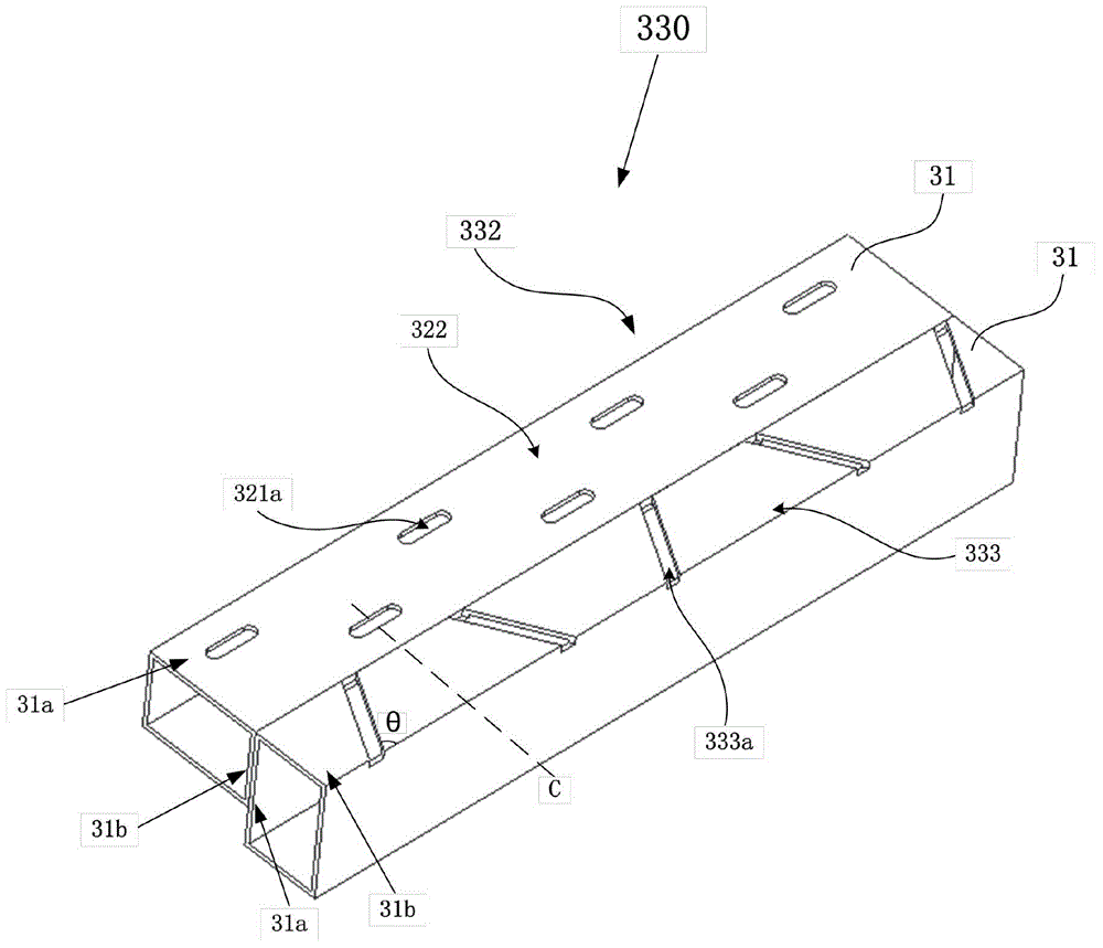
[0052] image 3 It is a structural schematic diagram of the slotted dual-waveguide antenna in Embodiment 3 of the present invention.

[0053] like image 3 As shown, in the third embodiment, the slotted dual-waveguide antenna 330 includes: two waveguides 31 and a slot group 332 .

[0054] The two slotted waveguides 31 are fixedly connected by the narrow side 31b of one waveguide 31 and the wide side 31a of the other waveguide 31 . like image 3 As shown, the lower narrow side 31 b of the upper waveguide 31 is fixedly connected to the upper wide side 31 a of the lower waveguide 31 .

[0055] The slit group 332 is provided on the adjacent broad side 31 a and narrow side 31 b of the two waveguides 31 . The fracture group 332 includes a first fracture group 333 and a second fracture group 322 .

[0056] The second slit group 322 ...


PUM


Abstract

The invention provides a crack double-waveguide antenna which is characterized in that the crack double-waveguide antenna comprises two waveguide tubes which are fixedly connected through any two sides and are respectively used for transmitting electromagnetic wave signals of different frequencies, and crack sets which are arranged on two adjacent sides of the two waveguide tubes and include a first set of cracks arranged on one side and a second set of cracks arranged on the other side, wherein the polarization direction of the first set of cracks is parallel to the length direction of the waveguide tubes, and the polarization direction of the second set of cracks is perpendicular to the length direction of the waveguide tubes. Because of a high degree of isolation between crack double-waveguide antennas, the channel correlation of signals can approach 0 when the signals are transmitted or receiving using the crack double-waveguide antennas. Therefore, the crack double-waveguide antenna of the invention has the advantages of small signal attenuation and strong anti-interference capability. In addition, the crack double-waveguide antenna can well support the MIMO technology and save space resources.

Description

technical field [0001] The invention relates to the field of wireless signal transmission, in particular to a slotted double waveguide antenna supporting MIMO technology. Background technique [0002] With the development of wireless technology, the application of wireless communication technology is becoming more and more extensive. In wireless communication systems, there are three main ways of signal transmission: free wireless, leaky coaxial cable, and slotted waveguide antenna. [0003] With the increase of the amount of communication information transmitted by people, in order to improve the system capacity under the condition that the existing bandwidth remains unchanged, a new communication technology emerges, that is, multiple-input multiple-output technology (MIMO technology). MIMO technology refers to the use of multiple transmitting antennas and receiving antennas at the transmitting end and receiving end, respectively, so that signals are transmitted and receiv...

Claims


Application Information

Patent Timeline
Patent Type & Authority Applications(China)
IPC IPC(8): H01Q13/22H01Q1/52H01Q21/00
Inventor 莫智超徐凡杨福慧
Owner 中电科微波通信(上海)股份有限公司
Why Eureka
Try Eureka