Laminated self-adaptive drip irrigation emitter and use method thereof

An emitter, self-adaptive technology, applied in application, botany equipment and method, watering device, etc., can solve the problems of single function of anti-clogging emitter products, insignificant effect of preventing biological clogging, and no energy-dissipating structural unit , to achieve the effect of enhancing self-cleaning ability, ensuring anti-clogging requirements, and improving energy dissipation efficiency

Active Publication Date: 2012-06-20
CHINA AGRI UNIV
View PDF8 Cites 7 Cited by
  • Summary
  • Abstract
  • Description
  • Claims
  • Application Information

AI Technical Summary

Problems solved by technology

Scholars in my country have also made some explorations to solve the problem of emitter blockage from the perspective of emitter structural design: for example, Fan Xingke of Northwest Agriculture and Forestry University (public number CN1636437A) disclosed a turbulent flow anti-clogging emitter flow channel structure design method, based on hydraulics The turbulent flow and eddy current theory in the paper uses an arc-shaped surface with the characteristics of a vortex surface on the side of the flow channel unit to avoid the precipitation of fine particles, but the effect on preventing biological clogging is not significant
Yang Peiling et al. (publication number CN1454459) disclose a drip irrigation emitter, which adopts the form of fractal flow channels to enhance the energy dissipat

Method used


Image

  • Laminated self-adaptive drip irrigation emitter and use method thereof
  • Laminated self-adaptive drip irrigation emitter and use method thereof
  • Laminated self-adaptive drip irrigation emitter and use method thereof

Examples


Example Embodiment

[0023] The present invention will be described in detail below in conjunction with the accompanying drawings and embodiments.

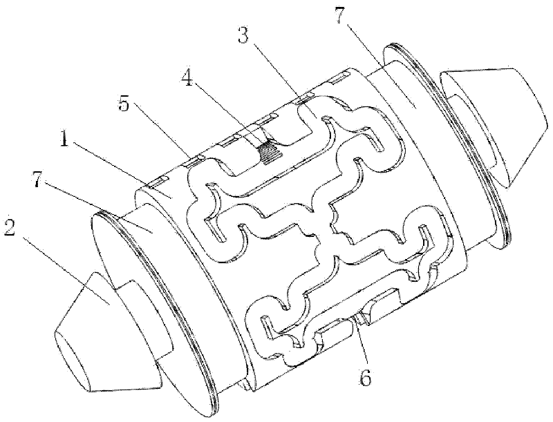
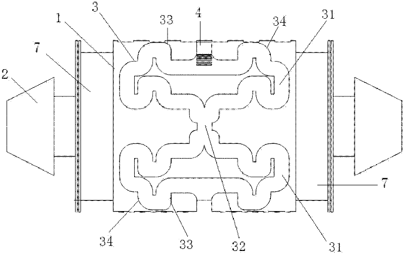
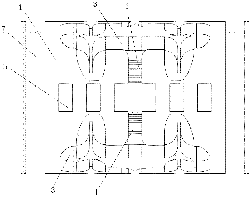
[0024] like figure 1 , figure 2 As shown, the present invention includes a hollow cylindrical emitter housing 1, and two ends of the emitter housing 1 are respectively provided with a pair of joints 2, and the butt joints 2 are used for docking with PE (polyethylene) pipes. The outer wall of the emitter shell 1 is symmetrically provided with two sets of curved tooth-shaped energy-dissipating flow channels 3, two sets of arc-tooth-shaped energy-dissipating flow channels 3 are arranged along the axial direction of the emitter shell 1, and two sets of arc-toothed energy-dissipating channels 3 The structures of the energy-dissipating flow channels 3 are the same, and there are wall water inlets 4 connected to the interior of the emitter shell 1. A structural area 5 and a slow-flow area 6 are arranged between the two sets of arc-tooth energy-dissipating ...


PUM


Abstract

The invention relates to a laminated self-adaptive drip irrigation emitter and a use method thereof; the laminated self-adaptive drip irrigation emitter is characterized by comprising a emitter shell body; both ends of the emitter shell body are respectively provided with a butting joint; two groups of arc tooth-shaped energy dissipation runners are arranged on the outer wall of the emitter shell body; a structure area and a buffer area are arranged between the two groups of arc tooth-shaped energy dissipation runners; positions on the two groups of arc tooth-shaped energy dissipation runners which are close to the structure area are provided with wall surface water inlets which are communicated with the inside of the emitter shell body, and the positions of the two groups of arc tooth-shaped energy dissipation runners which are close to the buffer area are provided with outlets which are communicated with the buffer area; both ends of the outer wall of the emitter shell body are respectively provided with a circle of water collection runner which is communicated with the buffer area; a capillary is wrapped outside the emitter shell body, and water outlets are arranged on one or two ends of the water collection runner on the capillary; positions in the emitter shell body which are close to butting joints on both ends are respectively provided with a water inlet and outlet laminate; two energy dissipation laminates are arranged between the two water inlet and outlet laminates; an elastic diaphragm is arranged between the two energy dissipation laminates; and the wall surface water inlets are arranged between the two energy dissipation laminates.

Description

technical field [0001] The invention relates to a drip irrigation emitter used in the field of water-saving irrigation and a usage method thereof, in particular to a laminated self-adaptive drip irrigation pipe (belt) emitter and a usage method thereof. Background technique [0002] Drip irrigation is considered to be the safest and most reliable irrigation method among modern irrigation methods due to its precise and controllable characteristics. However, natural water bodies contain a large amount of particulate matter, nutrients, organic matter, microorganisms, etc. more complicated. The emitter is the most critical part of the drip irrigation system. Its function is to make the pressurized water flow through the narrow and long channels or micropores inside it to fully dissipate energy, and then drip into the soil with a uniform and stable small flow rate. However, due to the need for energy dissipation of the emitter, the size of the flow channel is generally only abou...

Claims


Application Information

Patent Timeline
IPC IPC(8): B05B1/34B05B1/30A01G25/02
Inventor 李云开孙昊苏
Owner CHINA AGRI UNIV
Why Eureka
Try Eureka