Bevel gear drill clamp

A drilling jig, bevel gear technology, applied in the direction of clamping, manufacturing tools, support, etc., can solve the problem of low versatility of the three-jaw chuck, and achieve the effects of strong versatility, accurate positioning and high machining accuracy

Inactive Publication Date: 2012-06-20
JIANGSUSNGCHI GROUP
View PDF10 Cites 8 Cited by
  • Summary
  • Abstract
  • Description
  • Claims
  • Application Information

AI Technical Summary

Problems solved by technology

When machining screw holes, the existing technology uses a hydraulic three-jaw chuck to clamp, but

Method used


Image

  • Bevel gear drill clamp
  • Bevel gear drill clamp

Examples


Example Embodiment

[0009] The present technology will be further described below through embodiments in conjunction with the accompanying drawings.

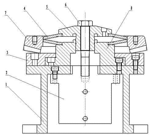
[0010] like figure 1 The shown bevel gear drilling fixture includes a base 1, a hydraulic cylinder 2, a backing plate 3, a spring expansion piece 4, a pressure plate 5, a bolt 6, and a mandrel 8. The hydraulic cylinder 2 , the backing plate 3 and the mandrel 8 are all fixed on the base 1 . The lower inner hole of the spring expansion sheet 4 is in clearance fit with the mandrel 8 . The steps of the pressing plate 5 are in clearance fit with the inner hole of the spring expansion sheet 4 . The tension bolt 6 is connected to the hydraulic cylinder 2. When working, the hydraulic cylinder 2 pulls the bolt 6 to move downward, so that the spring expansion piece 4 expands and tightens the workpiece 7.


PUM


Abstract

The invention provides a bevel gear drill clamp, which is strong in generality, accurate in location and capable of guaranteeing processing accuracy and comprises a cushion plate which is used for supporting an end face of a bevel gear to be processed and detachably connected on a base. A core shaft and a press plate penetrating through a central hole of the core shaft are fixed on the base, the outer sides of opposite end faces of the press plate and the core shaft are both provided with annular steps, an upper inner hole and a lower inner hole of a spring expansion hole at the upper portion of the cushion plate are respectively matched with the annular steps on the outer sides of the press plate and the core shaft, and a driving device capable of driving the press plate to move along the axial direction of the core shaft is arranged on the base.

Description

technical field [0001] The technology relates to a bevel gear drilling jig. Background technique [0002] The bevel gear is the driven gear in the rear axle of the car, and there are multiple screw holes on the back to connect with the differential case. When machining screw holes, the prior art uses a hydraulic three-jaw chuck to clamp, but due to the variety and shape of bevel gears, the versatility of the three-jaw chuck is not strong. Contents of the invention [0003] The purpose of this technology is to provide a bevel gear drilling jig with strong versatility, accurate positioning and guaranteed machining accuracy. [0004] The bevel gear drilling jig comprises a backing plate that is detachably connected to the base for supporting the end face of the bevel gear to be processed, and the base is fixed with a mandrel and a pressing plate that passes through the center hole on the mandrel. There are annular steps on the outside of the opposite end face of the pressur...

Claims


Application Information

Patent Timeline
IPC IPC(8): B23Q3/00
Inventor 朱江华邵钰钫
Owner JIANGSUSNGCHI GROUP
Why Eureka
Try Eureka