Torque-limiting-type contact non-return device

A backstop and contact technology, applied in the direction of transportation, packaging, conveyors, etc., can solve problems such as overload, damage, parking brake, etc., and achieve the effect of improving the safety factor of operation, facilitating centralized control, and high reliability

Active Publication Date: 2012-06-20
TAIAN ENDLESS MECHANICAL & ELECTRICAL TECH CO LTD
View PDF7 Cites 4 Cited by
  • Summary
  • Abstract
  • Description
  • Claims
  • Application Information

AI Technical Summary

Problems solved by technology

[0003] 1. When the belt conveyor is heavy-loaded and parked or braked in an emergency, most of the backstop torque borne by the backstop cannot be balanced, and even most of the load will be concentrated on one of the backstops. On the contrary, the load on the backstop of the driving device and related parts and components will increase, which may lead to overloading and damage of these parts and components, so that the belt conveyor cannot be reliably parked and braked, or even cause speeding, resulting in extreme serious consequence
[0004] 2. In the design of the main engine of the belt conveyor, when the backstop is selected, the backstop torque coefficient on the driving device is generally increased and a high-standard backstop is selected so that it can withstand the load of the entire belt conveyor alone. The required backstop torque will not only increase the equipment cost of the whole machine, but also may cause overloading of other parts and components, thereby reducing the backstop reliability of the whole machine

Method used


Image

  • Torque-limiting-type contact non-return device
  • Torque-limiting-type contact non-return device
  • Torque-limiting-type contact non-return device

Examples


Embodiment Construction

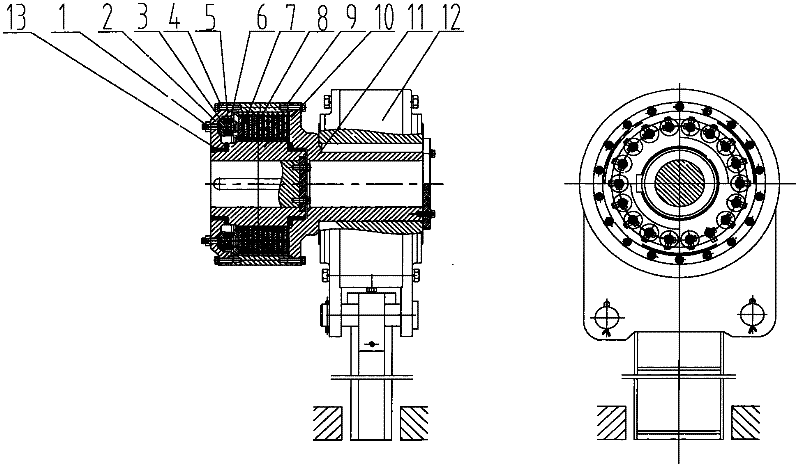
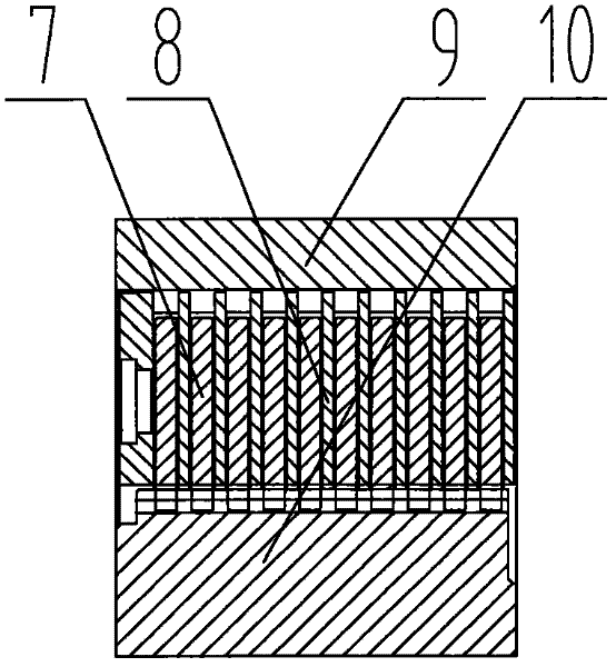
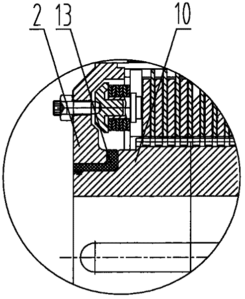
[0014] The preferred embodiment of the torque-limiting contact backstop of the present invention is as follows: figure 1 , figure 2 , image 3 , Figure 4 As shown, the torque-limiting contact backstop includes adjusting screw 1, support plate 2, adjusting washer 3, connecting bolt 4, guide sleeve 5, butterfly spring 6, dynamic friction plate set 7, static friction plate set 8, support sleeve 9 , Connecting sleeve 10, connecting disc 11, backstop 12 and protective sleeve 13.

[0015] The supporting plate 2 is connected with the supporting sleeve 9 through the connecting bolt 4, the supporting sleeve 9 is connected with the connecting plate 11 through the connecting bolt 4, and the connecting plate 11 is connected with the backstop 12 through a key.

[0016] The dynamic friction plate set 7 is embedded with the outer teeth of the connecting sleeve 10 through the inner teeth, and the static friction plate set 8 is embedded with the inner teeth of the support sleeve 9 through...


PUM


Abstract

The invention discloses a torque-limiting-type contact non-return device which comprises an adjusting screw, a support tray, an adjusting washer, a connecting bolt, a guide sleeve, a butterfly-shaped spring, a dynamic friction sheet group, a static friction sheet group, a support sleeve, a connecting sleeve, a connecting tray, a non-return device and a protecting jacket. The support tray is connected with the support sleeve through the connecting bolt; the support sleeve is connected with the connecting tray through the connecting bolt; the connecting tray is connected with the non-return device through a key; the dynamic friction sheet group is embedded in an external tooth of the connecting sleeve through an internal tooth; the static friction sheet group is embedded in the internal tooth of the support sleeve through the external tooth; the protecting jacket is arranged between the support tray and the connecting sleeve; and the front end of the adjusting washer is in clearance fit with the guide sleeve and is embedded in the guide sleeve. The torque-limiting-type non-return device is compact in structure, has high reliability, is convenient to control centrally, is suitable for an upper-conveying multi-drive belt-type conveyer, and can enable the non-return torque of each set of driving device to be limited in a specific range, thereby achieving the aim of balanced load operation of the non-return device, and the operating safety factor of the belt-type conveyor is improved.

Description

technical field [0001] The invention relates to a moment-limiting contact type backstop, which is mainly applied to a multi-drive upper belt conveyor. Background technique [0002] At present, the backstops used in belt conveyors in my country mainly include non-contact backstops and contact backstops. If the above two backstops are applied to multi-drive belt conveyors, they are usually A backstop must be installed on each set of driving devices. For this reason, the parts and components on each driving device are required to be basically balanced when the whole machine is reversed, that is, the backstop on each set of backstops must be balanced. The torque should be basically equal, but there are many problems in actual work: [0003] 1. When the belt conveyor is heavy-loaded and parked or braked in an emergency, most of the backstop torque borne by the backstop cannot be balanced, and even most of the load will be concentrated on one of the backstops. On the contrary, the...

Claims


Application Information

Patent Timeline
Patent Type & Authority Applications(China)
IPC IPC(8): B65G23/26
Inventor 周满山孙斌武蒋志成王建国李震马明明郑洲
Owner TAIAN ENDLESS MECHANICAL & ELECTRICAL TECH CO LTD
Why Eureka
Try Eureka