Rope driving mechanism frame, rope driving mechanism and engineering machinery

A rope drive and frame body technology is applied in the field of rope drive mechanisms, construction machinery, and rope drive mechanisms, and can solve the problems of accelerated rope wear, affecting the working reliability of the rope drive mechanism, and rope slippage.

Active Publication Date: 2012-06-20
SANY AUTOMOBILE MFG CO LTD
View PDF5 Cites 2 Cited by
  • Summary
  • Abstract
  • Description
  • Claims
  • Application Information

AI Technical Summary

Problems solved by technology

[0006] Although the above-mentioned rope drive mechanism can drive the moving parts of construction machinery, when the load is large and the working environment changes, t

Method used


Image

  • Rope driving mechanism frame, rope driving mechanism and engineering machinery
  • Rope driving mechanism frame, rope driving mechanism and engineering machinery
  • Rope driving mechanism frame, rope driving mechanism and engineering machinery

Examples


Embodiment Construction

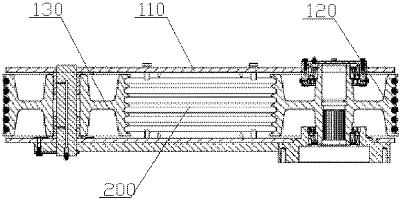
[0031] The applicant analyzed the reasons for the slipping of the rope drive mechanism described in the background art section. Please refer to Figure 4 , which shows a transverse cross-sectional view of the cable drive mechanism in the Background Art section. The contact portion between the rope 200 and the second runner 130 rope groove and the contact portion between the rope 200 and the first runner 120 rope groove form corresponding rope wrap angles respectively; Figure 4 As shown, when the radii of the second runner 130 and the first runner 120 are equal (the distance between the axis of rotation and the outer edge), the rope wrap angles formed on the second runner 130 and the first runner 120 are equal. is 180 degrees. After analysis, the applicant believes that: the reason for the slippage of the rope drive mechanism is that the rope wrap angle formed on the runner is too small, resulting in a decrease in the friction between the rope and the corresponding runner; a...


PUM


Abstract

The invention discloses a rope driving mechanism and a frame thereof and further relates to engineering machinery comprising the rope driving mechanism. The frame of the rope driving mechanism comprises a support, a first rotating wheel, a second rotating wheel and a third rotating wheel, the first rotating wheel and the second rotating wheel are respectively mounted on the support, the peripheries of the first rotating wheel and the second rotating wheel are respectively provided with a rope groove, the third rotating wheel is rotatably mounted on the support, the periphery of the third rotating wheel is also provided with a rope groove, the third rotating wheel and the second rotating wheel can rotate in two opposite directions, and the rotation axis of the third rotating wheel is overlapped with that of the second rotating wheel. Therefore, both a rope wrapping angle formed on the first rotating wheel and a rope wrapping angle formed on the second rotating wheel can be correspondingly increased. Furthermore, the contact length between a rope and each rotating wheel can be ensured, friction force between the rope and each rotating wheel is increased, slip of the rope is decreased, the reliability of the rope driving mechanism is improved, and abrasion of the rope is decelerated.

Description

technical field [0001] The invention relates to a rope driving technology, in particular to a frame body of a rope driving mechanism, and also relates to a rope driving mechanism including the frame body, and a construction machine including the rope driving mechanism. Background technique [0002] The rope drive mechanism is a commonly used drive mechanism for construction machinery. The construction machinery includes fixed parts and movable parts, and the movable parts are slidably or rotatably mounted on the fixed parts; in this case, the movable parts can be driven to move in a predetermined way through the rope drive mechanism. For example: in the telescopic belt conveying machine, the telescopic arm is slidably installed on the body; the telescopic arm can perform telescopic movement relative to the body under the drive of the rope drive mechanism. [0003] Please refer to Figure 1 to Figure 3 , figure 1 is a structural schematic diagram of a rope drive mechanism;...

Claims


Application Information

Patent Timeline
IPC IPC(8): F16H19/06
Inventor 高晓汉黄海日姜波
Owner SANY AUTOMOBILE MFG CO LTD
Why Eureka
Try Eureka