Laser displacement transducer mounting support provided with adjusting and self-calibrating structure

A technology of laser displacement and mounting brackets, applied in the direction of using optical devices, instruments, measuring devices, etc., can solve the problems of lack of benchmarks, trouble, difficulty in checking performance parameters, etc., and achieve high resolution, convenient use, and high control accuracy. Effect

Inactive Publication Date: 2012-06-20
SHANGHAI INST OF TECH
View PDF5 Cites 4 Cited by
  • Summary
  • Abstract
  • Description
  • Claims
  • Application Information

AI Technical Summary

Problems solved by technology

However, such adjustments at the application site require some auxiliary materials, devices or tools to complete, which is cumbersome and lacks corresponding benchmarks.
At the same time, it is difficult to check the performance parameters of the laser displacement sensor during the installation and commissioning of the field application and after a period of use

Method used


Image

  • Laser displacement transducer mounting support provided with adjusting and self-calibrating structure
  • Laser displacement transducer mounting support provided with adjusting and self-calibrating structure
  • Laser displacement transducer mounting support provided with adjusting and self-calibrating structure

Examples


Embodiment Construction

[0018] The present invention will be further described below in conjunction with the accompanying drawings and embodiments.

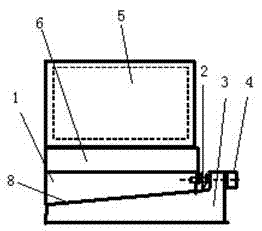
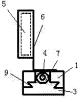
[0019] Such as figure 1 , as shown in 2, the laser displacement sensor mounting bracket with adjustment and self-calibration structure of the present invention includes an upper adjustment bracket 1, a preload spring 2, a lower adjustment bracket 3, an adjustment bolt 4, a sensor base frame 6, and a dial 7 Wait.

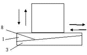
[0020] The lower end surface of the upper adjustment frame 1 and the upper end surface of the lower adjustment frame 3 are connected through a dovetail groove structure 9 with a slope 8. The right end surface of the upper adjustment frame 1 is provided with an adjustment screw hole, and the right side of the lower adjustment frame 3 is convex. Adjusting bolts 4 are connected in the table, and the upper adjusting frame 1 and the lower adjusting frame 3 are adjustable through the adjusting bolts 4 and threaded holes, and the adjusting bolts 4 a...


PUM


Abstract

The invention relates to a laser displacement transducer mounting support provided with an adjusting and self-calibrating structure. The laser displacement transducer mounting support comprises an upper adjusting frame, a pre-tightening spring, a lower adjusting frame, an adjusting bolt and a transducer base frame provided with a transducer. The transducer base frame is fixed on the upper adjusting frame. The lower end face of the upper adjusting frame and the upper end face of the lower adjusting frame are connected by virtue of a dovetail groove structure with inclination, the right end face of the upper adjusting frame is provided with an adjusting screwed hole, a right boss of the lower adjusting frame is internally connected with the adjusting bolt, the upper adjusting frame and the lower adjusting frame are connected in an adjustable way by virtue of the adjusting bolt and the screwed hole, the pre-tightening spring is sheathed outside the adjusting bolt, and the two ends of the pre-tightening spring are respectively connected with the right end face of the upper adjusting frame and the inner end face of the right boss of the lower adjusting frame in a compressed manner. When the laser displacement transducer mounting support provided by the invention is used for carrying out adjustment and preliminary calibration in a laser displacement transducer application field, auxiliary materials, devices or tools are not required to complete the adjustment and preliminary calibration, the laser displacement transducer mounting support provided by the invention is convenient to use and is provided with a corresponding standard, and displacement control accuracy is high.

Description

technical field [0001] The invention relates to a sensor mounting bracket, in particular to a laser displacement sensor mounting bracket. Background technique [0002] The existing laser displacement sensor mounting bracket is only used for the installation and fixation of the laser displacement sensor. In actual use, it is often necessary to properly adjust and initially calibrate the distance between the installation position of the laser displacement sensor and the measured object (calibration ). However, such adjustment in the application field needs some auxiliary materials, devices or tools to complete, which is cumbersome and lacks corresponding benchmarks. At the same time, it is difficult to check the performance parameters of the laser displacement sensor during the installation and debugging of the field application and after a period of use. Contents of the invention [0003] The present invention is to provide a laser displacement sensor mounting bracket wit...

Claims


Application Information

Patent Timeline
Patent Type & Authority Applications(China)
IPC IPC(8): G01B11/02
Inventor 石钢胡飒英季国荣
Owner SHANGHAI INST OF TECH
Why Eureka
Try Eureka