

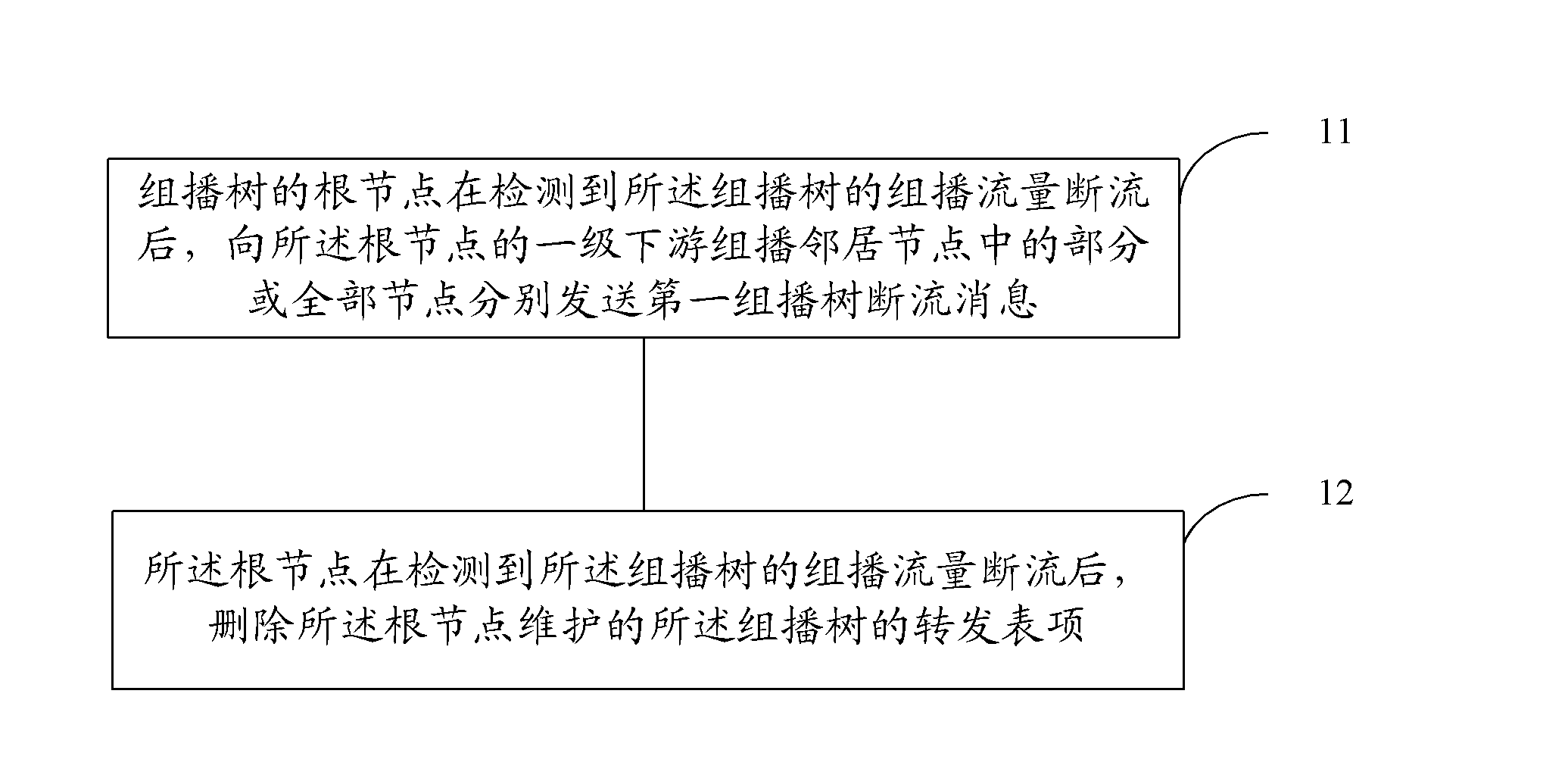
Forwarding entry deletion method and root node
A technology for forwarding table items and root nodes, applied in the field of communication, can solve problems such as occupying a lot of network resources, and achieve the effect of fast deletion
- Summary
- Abstract
- Description
- Claims
- Application Information
AI Technical Summary
Problems solved by technology
Method used
Image

Examples
no. 2 example
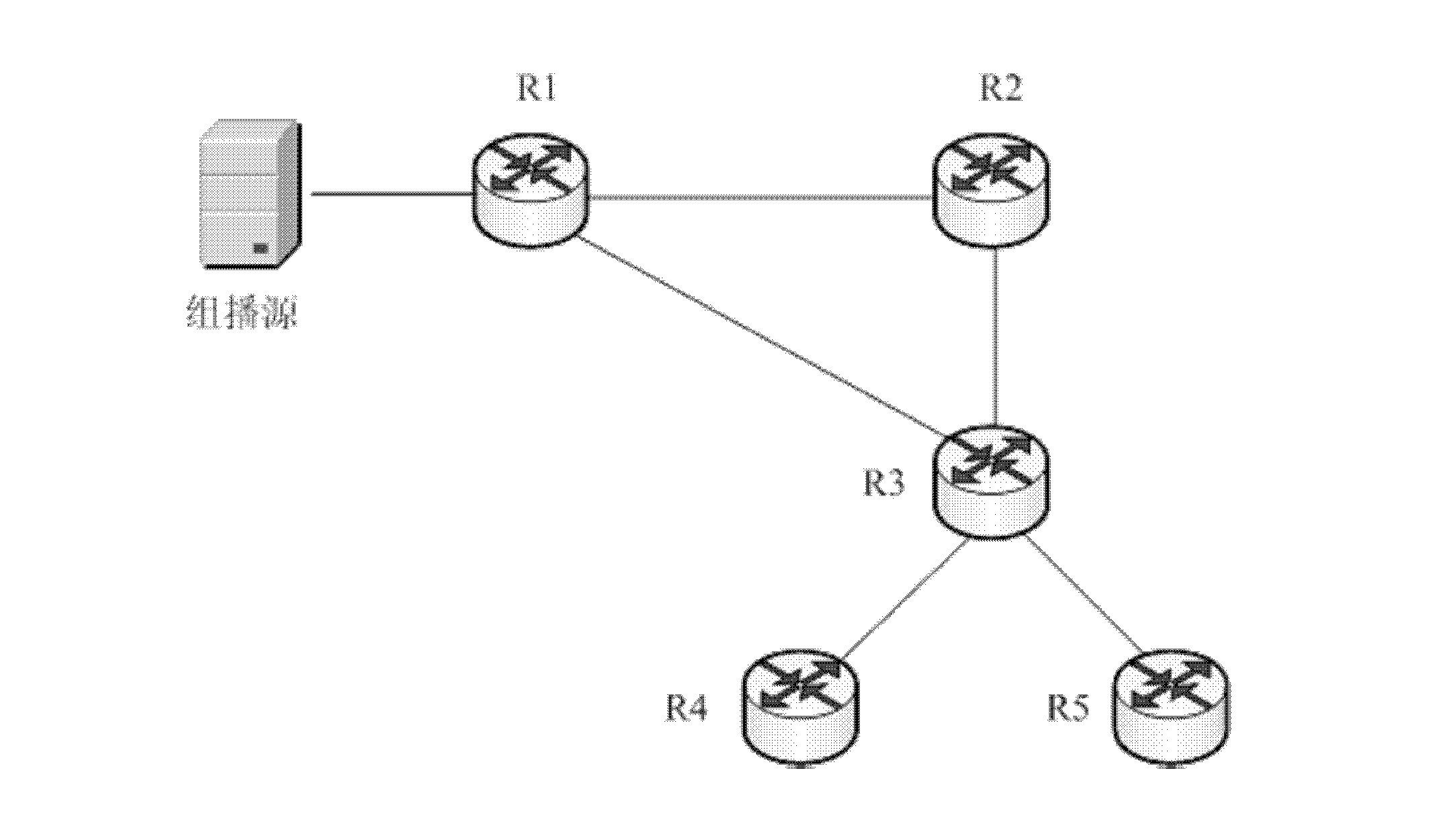
[0039] figure 2 Shown is a schematic diagram of the multicast tree in the second embodiment.
[0040] exist figure 2 Among them, the root node of the multicast tree is router 1 (R1), and R1 is a source designated router (DR); router 2 (R2) is the first-level downstream multicast neighbor node of R1; router 3 (R3) is the The second-level downstream multicast neighbor node; router 4 (R4) is the third-level downstream multicast neighbor node of R1, and R4 is also a rendezvous node (RP); router R5 is the fourth-level downstream multicast neighbor node of R1, and R5 is a user End Designated Router (DR), which is the terminal leaf node of the multicast tree. The multicast tree includes R1, R2, R3, R4 and R5.
[0041] When R1 detects that the multicast traffic of the multicast tree is disconnected, it sends a first multicast tree disconnection message to R2 according to the forwarding entry of the multicast tree on R1.
[0042] After sending the first multicast tree disconnecti...
no. 3 example
[0052] In this embodiment, the structure of the multicast tree is the same as that in the second embodiment figure 2 The structures of the multicast trees shown are the same, that is, the root node of the multicast tree is router 1 (R1), and R1 is a source designated router (DR); router 2 (R2) is the first-level downstream multicast neighbor node of R1 ;Router 3 (R3) is the second-level downstream multicast neighbor node of R1; router 4 (R4) is the third-level downstream multicast neighbor node of R1, and R4 is also a rendezvous node (RP); router 5 (R5) is R 1 The four-level downstream multicast neighbor node of R5, R5 is a designated router (DR) at the user end, and is the terminal leaf node of the multicast tree. The multicast tree includes R1, R2, R3, R4 and R5.
[0053] The processing method in this embodiment is as follows.
[0054] When R1 detects that the multicast traffic of the multicast tree is disconnected, it sends a first multicast tree disconnection message to...
no. 4 example
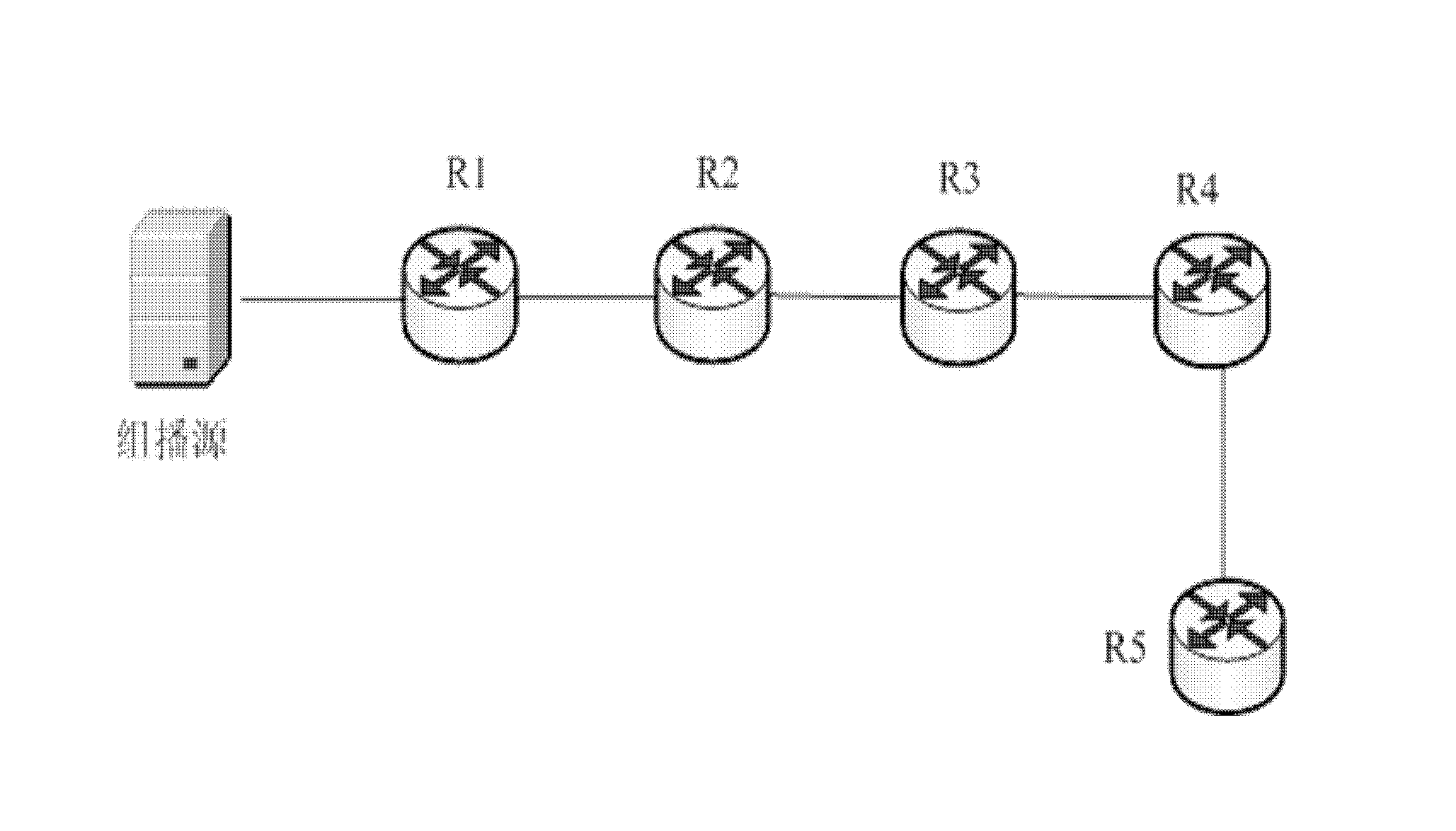
[0064] image 3 It is a schematic diagram of a multicast tree according to Embodiment 4 of the present invention.
[0065] exist image 3 Among them, the root node of the multicast tree is router 1 (R1), and R1 is a source designated router (DR); router 2 (R2) is the rendezvous node (RP) of the multicast tree, and the RP is not in the On the forwarding path of the multicast tree; router 3 (R3) is the first-level downstream multicast neighbor node of R1; router 4 (R4) and router 5 (R5) are the second-level downstream multicast neighbor nodes of R1, and R4 and R5 are The two client designated routers (DRs) are the end leaf nodes of the multicast tree. The multicast tree includes R1, R3, R4, R5 and RP.
[0066] The processing method in this embodiment is as follows.
[0067] When R1 detects that the multicast traffic of the multicast tree is disconnected, it sends an RP multicast tree disconnection message to the RP, that is, R2. In addition, R1 also sends the first multicas...
PUM
 Abstract
Description
Claims
Application Information