Remote intelligent monitoring system for street lamp

An intelligent monitoring system and intelligent control technology, applied in the direction of energy-saving incandescent lamps, energy-saving lighting, lighting devices, etc., can solve the problems of large power consumption, affecting citizens' travel, and unable to repair and replace in time, so as to improve work efficiency and restrain excessive energy. consumption effect

Inactive Publication Date: 2012-06-20
扬州恒格节能科技有限公司
View PDF0 Cites 6 Cited by
  • Summary
  • Abstract
  • Description
  • Claims
  • Application Information

AI Technical Summary

Problems solved by technology

The main manifestations are as follows: First, the lamp holders of street lamps are often damaged, which can only be discovered by night patrols of management personnel or citizens’ reports, and cannot be repaired and replaced in time, especially in small streets and alleys, where the lighting rate is not high, which affects citizens’ night travel; Effective preventive measures, cable theft occurs from time to time, especially in the outer ring or suburban junctions, causing huge losses to the country; Fourth, the existing street lamp control methods cannot meet special climate conditions (cloudy days, wind and dust storms) ) or the needs of major mass festivals, etc.
[0003] Therefore, the existing street lamp control and management methods with many control points can no longer meet the development and management needs of street lamps.
However, the huge street lighting system and landscape lighting system need to consume a lot of electricity, which will undoubtedly bring double pressure on the city's power supply and financial expenditure.

Method used


Image

  • Remote intelligent monitoring system for street lamp
  • Remote intelligent monitoring system for street lamp
  • Remote intelligent monitoring system for street lamp

Examples


Embodiment Construction

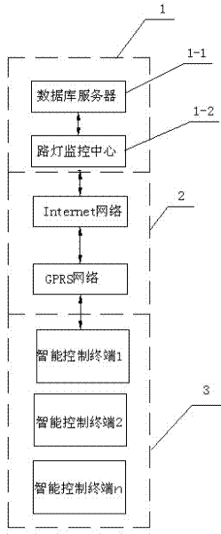
[0017] Such as figure 1 As shown, the present invention is mainly composed of three parts: a monitoring center 1, a communication module 2 and at least one group of intelligent control terminals 3, and the monitoring center 1 and each group of intelligent control terminals 3 are connected through the communication module 2 respectively.

[0018] The monitoring center 1 includes a database server 1-1 and a street lamp monitoring center 1-2.

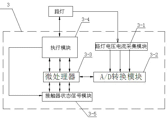
[0019] Such as figure 2 As shown, the intelligent control terminal 3 is provided with at least one set of street lamp voltage and current acquisition module 3-1, A / D conversion module 3-2, microprocessor 3-3, execution module 3-4 and contactor status signal module 3-5 .

[0020] The output ends of the street lamp voltage and current acquisition modules 3-1 of each group are respectively connected to the input ends 3-2 of the A / D conversion module, and the A / D conversion module 3-2 is connected with the execution module 3-5 through the m...


PUM


Abstract

The invention provides a remote intelligent monitoring system for a street lamp and relates to the technical field of automatic management of the street lamp. The remote intelligent monitoring system comprises a monitoring center, a communication module and at least one set of intelligent control terminals, wherein the monitoring center and each set of the intelligent control terminals are respectively in communication connection through the communication module. The remote intelligent monitoring system for the street lamp is used for dynamically monitoring and controlling a running environment of the street lamp by a built-in special power-saving optimizing device meeting the working characteristics of the street lamp, on the basis of a digital control technology of a microprocessor and according to the practical working conditions of severe environments of majority power supply grids of the street lamp and relative extensive cost management. The power required by the street lamp during the working process is timely adjusted according to the acquired related running parameters of the street lamp and the practically required power is accurately matched with the input power under the condition of ensuring the normal working of the street lamp, thereby restraining the exceeding energy consumption, increasing the working efficiency of the lamp and achieving the dual purpose of saving power and protecting the lamp.

Description

technical field [0001] The invention relates to the technical field of street lamp automation management. Background technique [0002] With the continuous expansion of the urban area, the urban lighting standards continue to improve, and the night life of urban residents continues to enrich, but the management of urban street lights is seriously lagging behind. The main manifestations are as follows: First, the lamp holders of street lamps are often damaged, which can only be discovered by night patrols of management personnel or citizens’ reports, and cannot be repaired and replaced in time, especially in small streets and alleys, where the lighting rate is not high, which affects citizens’ night travel; Effective preventive measures, cable theft occurs from time to time, especially in the outer ring or suburban junctions, causing huge losses to the country; Fourth, the existing street lamp control methods cannot meet special climate conditions (cloudy days, wind and dust ...

Claims


Application Information

Patent Timeline
IPC IPC(8): H05B39/04H05B41/36
CPCY02B20/14Y02B20/72Y02B20/00
Inventor 葛三春吴凤锦张辉杨荣海
Owner 扬州恒格节能科技有限公司
Why Eureka
Try Eureka