
Electricity saver for cold light source

A cold light source and power saving technology, applied in the direction of light source, electric light source, electrical components, etc., can solve the problems of shortened service life, waste of electric energy, increased power consumption, etc., and achieve the goals of improving efficiency, convenient use, and reducing power consumption Effect

Inactive Publication Date: 2009-01-28
杭州科丰电子股份有限公司
View PDF0 Cites 1 Cited by
  • Summary
  • Abstract
  • Description
  • Claims
  • Application Information

AI Technical Summary

Problems solved by technology

[0002] At present, the fluorescent lamps (a kind of cold light source) installed in most houses are directly connected in parallel to the grid. The voltage at both ends of the fluorescent lamps fluctuates with the fluctuation of the grid voltage. When the grid voltage increases, the power consumption of fluorescent lamps As the power grid voltage increases, the amount will increase over time, which will inevitably cause a great waste of electric energy, accelerate the aging of fluorescent lamps, and shorten their service life.

Method used


Image

  • Electricity saver for cold light source
  • Electricity saver for cold light source

Examples


Embodiment 1

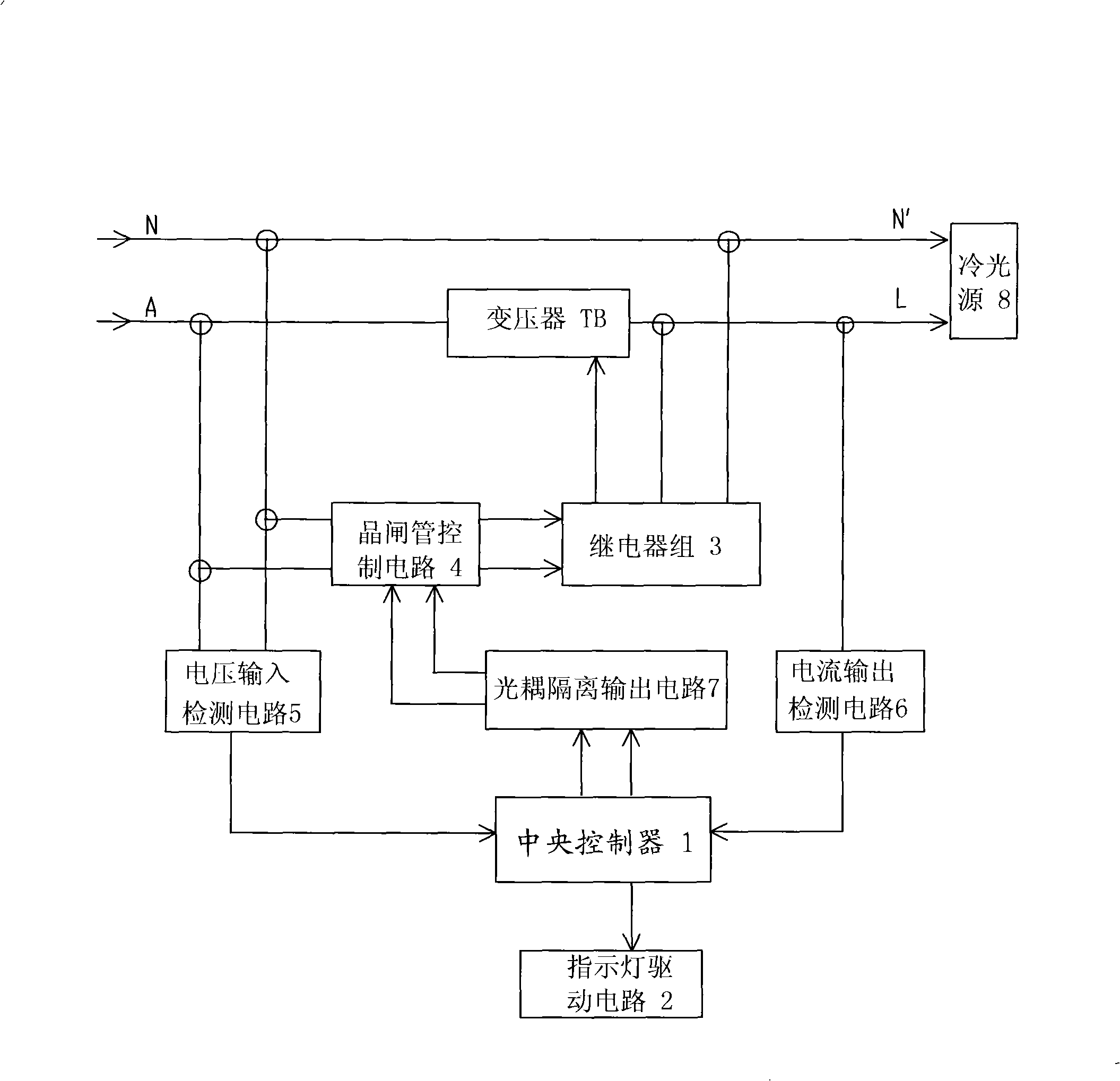
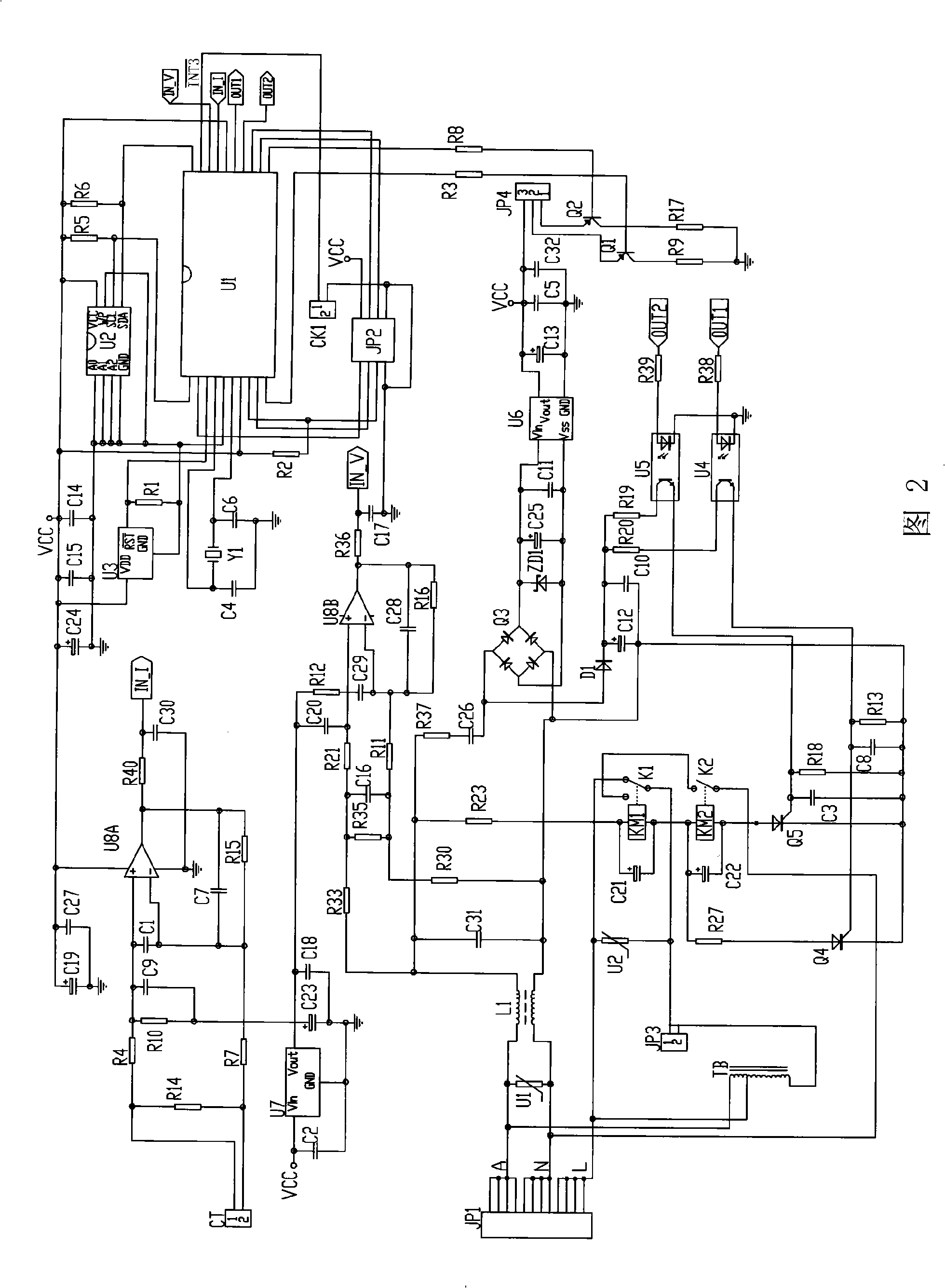
[0011] See figure 1 -2. The cold light source power saver of this embodiment includes: a central controller 1, an indicator light drive circuit 2, a transformer TB, a relay group 3, a thyristor control circuit 4, a voltage input detection circuit 5, a current output detection circuit 6 and an optocoupler Isolated output circuit 7.

[0012] The central controller 1 can adopt a single-chip microcomputer U1 or other intelligent controllers.

[0013] See figure 1 , the load terminal of the cold light source power saver (that is, the load live wire terminal L and the load neutral wire terminal N') is used to connect the cold light source 8. The power input terminal of the transformer TB used to control the load supply voltage is connected to the mains live wire input terminal A, and the power output terminal of the transformer TB is connected to the load live wire terminal L; the voltage signal output of the voltage input detection circuit 5 used to detect the mains voltage term...


PUM


Abstract

In order to solve the technical problems of reducing the electric power consumption of a cold light source and prolonging the service life thereof, the invention provides an electricity saver for the cold light source. The electricity saver comprises a central controller, a transformer, a relay assembly, a thyristor control circuit, a voltage input detection circuit and a current output detection circuit, wherein the input end of a power supply of the transformer used for controlling the load power supply voltage is connected with the input end of a live wire of the commercial power, the output end of the power supply of the transformer is connected with the terminal of the load live wire; the voltage input detection circuit used for detecting the voltage of the commercial power is connected with the detecting end of the voltage of the central controller, and the current output detection circuit used for detecting the load current is connected with the detecting end of the load current of the central controller; the control output end of the central controller is connected with the control input of the thyristor control circuit, and the output end of the control power supply of the thyristor control circuit is connected with the input end of the control power supply of the relay assembly; and the control output end of the relay assembly is connected with the control input end of the power supply of the transformer.

Description

technical field [0001] The invention relates to a cold light source power saver. Background technique [0002] At present, the fluorescent lamps (a kind of cold light source) installed in most houses are directly connected in parallel to the grid. The voltage at both ends of the fluorescent lamps fluctuates with the fluctuation of the grid voltage. When the grid voltage increases, the power consumption of fluorescent lamps The amount of electricity increases with the increase of the grid voltage. This will inevitably cause a great waste of electric energy, accelerate the aging of fluorescent lamps and shorten their service life. Contents of the invention [0003] The technical problem to be solved by the present invention is to provide a cold light source power saver that can reduce the energy consumption of the cold light source and prolong its service life. [0004] In order to solve the above technical problems, the cold light source power saver of the present inventio...

Claims


Application Information

Patent Timeline
Patent Type & Authority Applications(China)
IPC IPC(8): H05B41/36H05B41/295
Inventor 李敏倪仕杰林新朋郑大乐
Owner 杭州科丰电子股份有限公司
Learn More