Radiating system of box type machine case communication device, box type machine case and communication device

A heat dissipation system and communication equipment technology, applied in the construction parts of electrical equipment, cooling/ventilation/heating transformation, electrical components, etc., can solve problems such as circuit board corrosion, water film generation, water vapor turning into condensation, etc. Condensation and water film, the effect of avoiding condensation corrosion

Active Publication Date: 2014-09-03
HUAWEI TECH CO LTD
View PDF4 Cites 0 Cited by
  • Summary
  • Abstract
  • Description
  • Claims
  • Application Information

AI Technical Summary

Problems solved by technology

[0008] However, the cooling effect of the box-type full exhaust system can easily cause water vapor to condense, thereby forming a water film and causing corrosion of the circuit board.

Method used


Image

  • Radiating system of box type machine case communication device, box type machine case and communication device
  • Radiating system of box type machine case communication device, box type machine case and communication device
  • Radiating system of box type machine case communication device, box type machine case and communication device

Examples


Embodiment 1

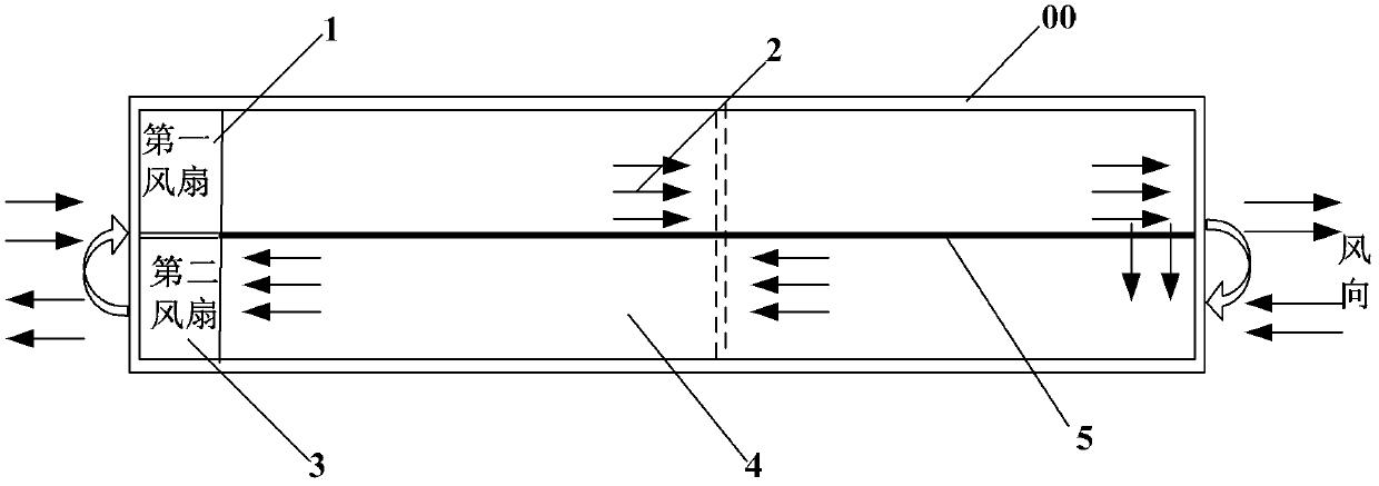
[0036] Such as image 3 As shown, the heat dissipation system of the box-type case communication equipment includes a case 00 , a first fan 1 , a second fan 3 and an adjustable windshield partition 5 . Among them, the arrow indicates the airflow direction.

[0037] There are ventilation holes on the left and right side walls of the chassis 00, and the adjustable windshield partition 5 is parallel to the airflow generated by the first fan 1 and the second fan 3, and is parallel to the circuit board slots on the chassis 00, so that the chassis 00 It is divided into upper and lower layers, forming two heat dissipation channels, the upper heat dissipation channel 2 and the lower heat dissipation channel 4, so as to prevent the cooling air generated by the fan from completely circulating inside the chassis 00. There are through holes on the adjustable windshield partition 5 to communicate with the upper heat dissipation channel 2 and the lower heat dissipation channel 4. According...

Embodiment 2

[0044] This embodiment is similar to the first embodiment, except that the position of the second fan 3 in the lower cooling channel 4 is changed. Such as Figure 4 As shown, the second fan 3 is located at the right end of the cooling channel 4 below, and becomes a fan blowing air to the inside of the chassis 00 .

[0045] In this embodiment, a fan is provided at the right end of the lower heat dissipation channel, which is more conducive to heat dissipation.

Embodiment 3

[0047] This embodiment is similar to the first embodiment, except that the position of the first fan 1 in the upper cooling channel 2 is changed. Such as Figure 5 As shown, the first fan 1 is located at the right end of the upper cooling channel 2 and becomes a fan blowing air to the outside of the chassis 00 .

[0048] In this embodiment, a fan is provided at the right end of the upper heat dissipation channel, which is more conducive to heat dissipation.


PUM


Abstract

The invention relates to a heat dissipation system for a box-type case communication device, a box-type case and a box-type case communication device. The heat dissipation system includes upper and lower heat dissipation channels, and the upper and lower heat dissipation channels respectively have an air outlet and an air inlet. The air inlet and air outlet of the upper and lower heat dissipation channels are respectively located on the side walls of the box-type chassis, and the air inlet of the upper heat dissipation channel is located above the air outlet of the lower heat dissipation channel. By arranging a windshield baffle in the box-type chassis, a circulating air flow is generated in the box-type chassis, so that the heat emitted by the circuit board is circulated in the box-type chassis through the air flow, so as to ensure that the temperature in the box-type chassis reaches the level to prevent water vapor from becoming condensation. Even the degree of water film prevents the generation of condensation and water film, and prevents the circuit board from being corroded by condensation.

Description

technical field [0001] The invention relates to the heat dissipation technology of communication equipment, in particular to a heat dissipation system of a box-type case communication device, a box-type case and a box-type case communication device. Background technique [0002] The installation environment of communication equipment has strict temperature and humidity requirements, but with the development of communication technology, communication equipment may be installed in a humid environment with high dust and salt mist concentration. Moreover, due to the capacity upgrade of communication equipment, the power consumption of both box-type products and box-type products is increasing, and fans need to be used for heat dissipation and air cooling. However, if air cooling is performed in a harsh environment, the circuit boards of communication equipment are more likely to corrode, affecting communication quality or even interrupting communication services, and increasing ...

Claims


Application Information

Patent Timeline
Patent Type & Authority Patents(China)
IPC IPC(8): H05K7/20
CPCH05K7/20127H05K7/20563H05K7/20145
Inventor 陈刚张寿开舒利文唐卫东
Owner HUAWEI TECH CO LTD
Why Eureka
Try Eureka