Spray head tilting mechanism

A technology of tilting mechanism and nozzle, which is applied in the field of water jet progressive forming, can solve the problems affecting forming efficiency and forming precision, and achieve high forming efficiency and forming precision

Active Publication Date: 2012-06-27
SHENZHEN INST OF ADVANCED TECH CHINESE ACAD OF SCI
View PDF5 Cites 5 Cited by
  • Summary
  • Abstract
  • Description
  • Claims
  • Application Information

AI Technical Summary

Problems solved by technology

However, in the existing nozzle tilting mechanism, the contact point between the water jet and the surface of the workpiece is changed during the tilting p

Method used


Image

  • Spray head tilting mechanism
  • Spray head tilting mechanism
  • Spray head tilting mechanism

Examples


specific Embodiment approach

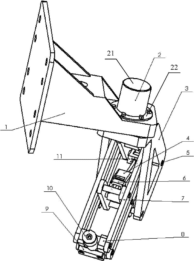
[0027] Please refer to Figure 5 , the specific implementation is as follows: first, the linear motor 4 drives the parallel rod hinge mechanism 7 to make the nozzle 10 tilt to the required angle value; after the angle is determined, the rotary drive motor 2 drives the turret 3 and the following connected mechanisms Rotate to adjust the direction of the inclination angle of the spray head 10, and after the inclination direction is determined, the inclination posture of the spray head 10 can be maintained. The next time you adjust the tilt posture, just follow the above steps to readjust.

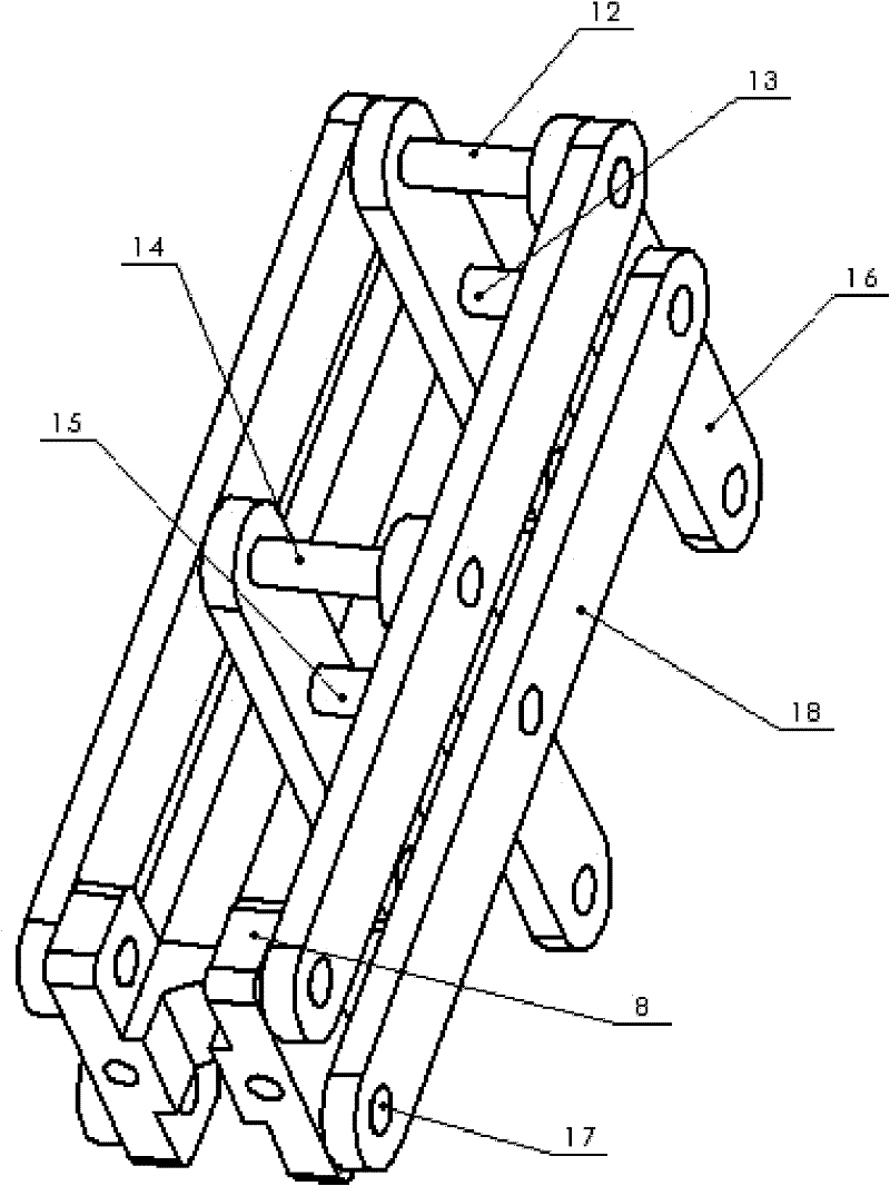
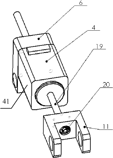
[0028] The rotary drive motor 2 is used to drive the rotation of the turret 3, so as to adjust the direction of the inclination angle of the nozzle 10; the linear motor 4 installed in the parallel rod hinge mechanism 7 is used to drive the parallel rod hinge mechanism 7 to realize the adjustment of the nozzle 10 The size of the inclination angle in a certain direction. In addition, the para...


PUM


Abstract

The invention relates to a spray head tilting mechanism, which comprises a fixed cantilever, a rotary driving motor fixedly arranged on the fixed cantilever, a rotating frame arranged at the rotary driving motor, a parallel rod hinge mechanism arranged at the rotating frame and fixedly provided with a spray head and a linear motor driving the parallel rod hinge mechanism,. The parallel rod hinge mechanism includes at least two spindles arranged in parallel and having the same movement track, at least two connection rods arranged in parallel and having the same movement track, and a plurality of fixed pins connecting the spindles and the connection rods and enabling the spindles and the connection rods to be arranged in interval. One ends of the connection rods suspend and are fixedly provided with sprayer heads. The rotating frame and the parallel rod hinge mechanism rotate around the driving motor under the rotation of the rotary driving motor, the parallel rod hinge mechanism moves through being driven by the linear motor and can make the spray head rotate around a preset forming point, the fixation of the forming point position is ensured, and higher forming efficiency and forming precision are realized.

Description

【Technical field】 [0001] The invention relates to a water jet progressive forming technology, in particular to a nozzle tilting mechanism. 【Background technique】 [0002] Water jet incremental forming technology is a comprehensive and applied advanced manufacturing technology based on sheet metal single point incremental forming technology and high-pressure water jet technology. Its characteristic is based on the mechanism of "layered manufacturing" in rapid proto The three-dimensional model is discretized into a series of two-dimensional layers along an appropriate direction, and layered plastic processing is performed on the metal sheet on the simplified two-dimensional layer. [0003] During the progressive forming process, there is a certain angle between the jet formed by the nozzle and the surface of the workpiece. When the posture of the nozzle remains unchanged, the angle between the jet formed by the nozzle and the surface of the workpiece becomes smaller and smalle...

Claims


Application Information

Patent Timeline
IPC IPC(8): B21D26/021
Inventor 何凯李全昌毛贺李赳华罗群杜如虚
Owner SHENZHEN INST OF ADVANCED TECH CHINESE ACAD OF SCI
Why Eureka
Try Eureka