Direction-variable cutting tool

A kind of cutting tool and variable technology, applied in the direction of manufacturing tools, metal processing machinery parts, driving devices, etc., can solve the problems of inability to cut products, restrict the mechanical manufacturing process of products, etc., and achieve the effect of effective cutting and perfect cutting.

Inactive Publication Date: 2012-06-27
GOALTECH
View PDF5 Cites 0 Cited by
  • Summary
  • Abstract
  • Description
  • Claims
  • Application Information

AI Technical Summary

Problems solved by technology

However, if the CNC milling machine machining center using the above-mentioned tools encounters a half-groove product that does not penetrate the inner hole wall, these general-purpose tools are restricted and cannot perform effective cutting on this type of product, which restricts the mechanical properties of the product. Manufacturing process

Method used


Image

  • Direction-variable cutting tool
  • Direction-variable cutting tool
  • Direction-variable cutting tool

Examples


Embodiment Construction

[0014] The technical solutions in the embodiments of the present invention will be clearly and completely described below in conjunction with the accompanying drawings in the embodiments of the present invention. Obviously, the described embodiments are only some of the embodiments of the present invention, not all of them. Based on the embodiments of the present invention, all other embodiments obtained by persons of ordinary skill in the art without making creative efforts belong to the protection scope of the present invention.

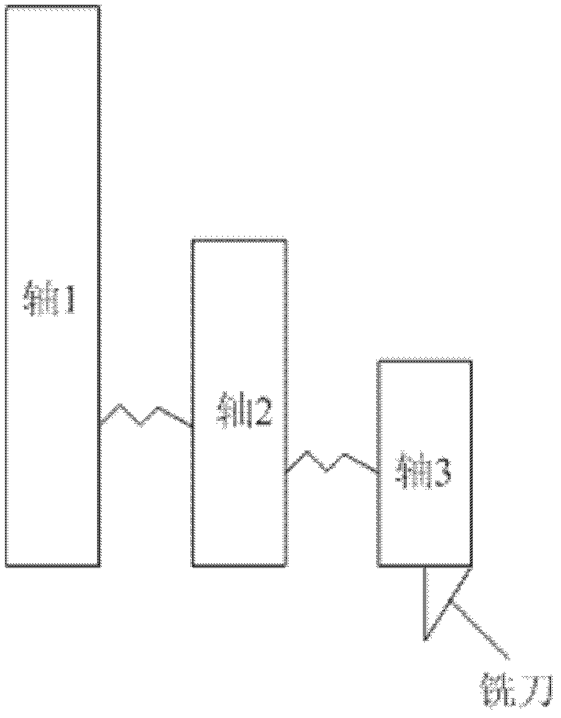
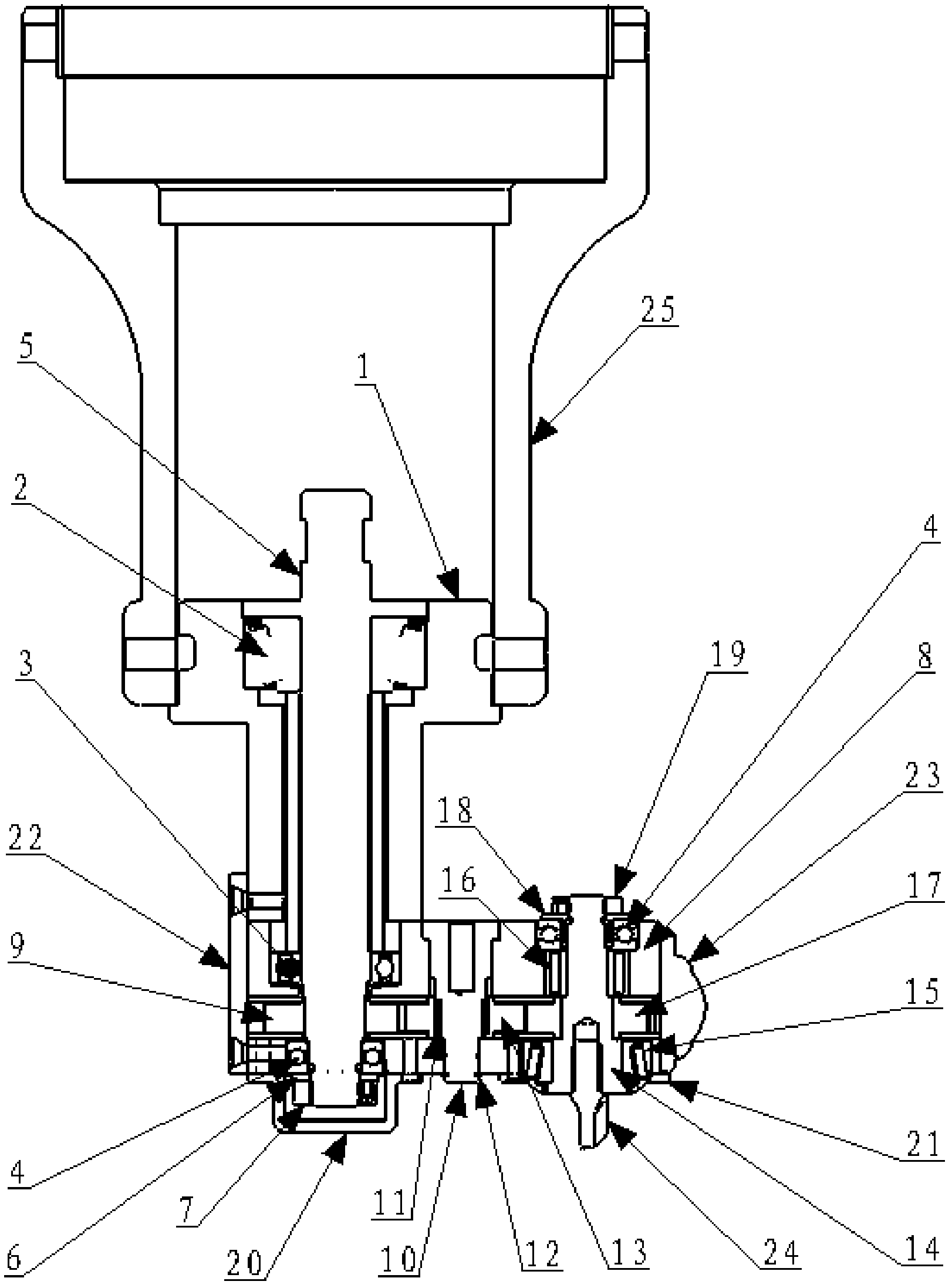
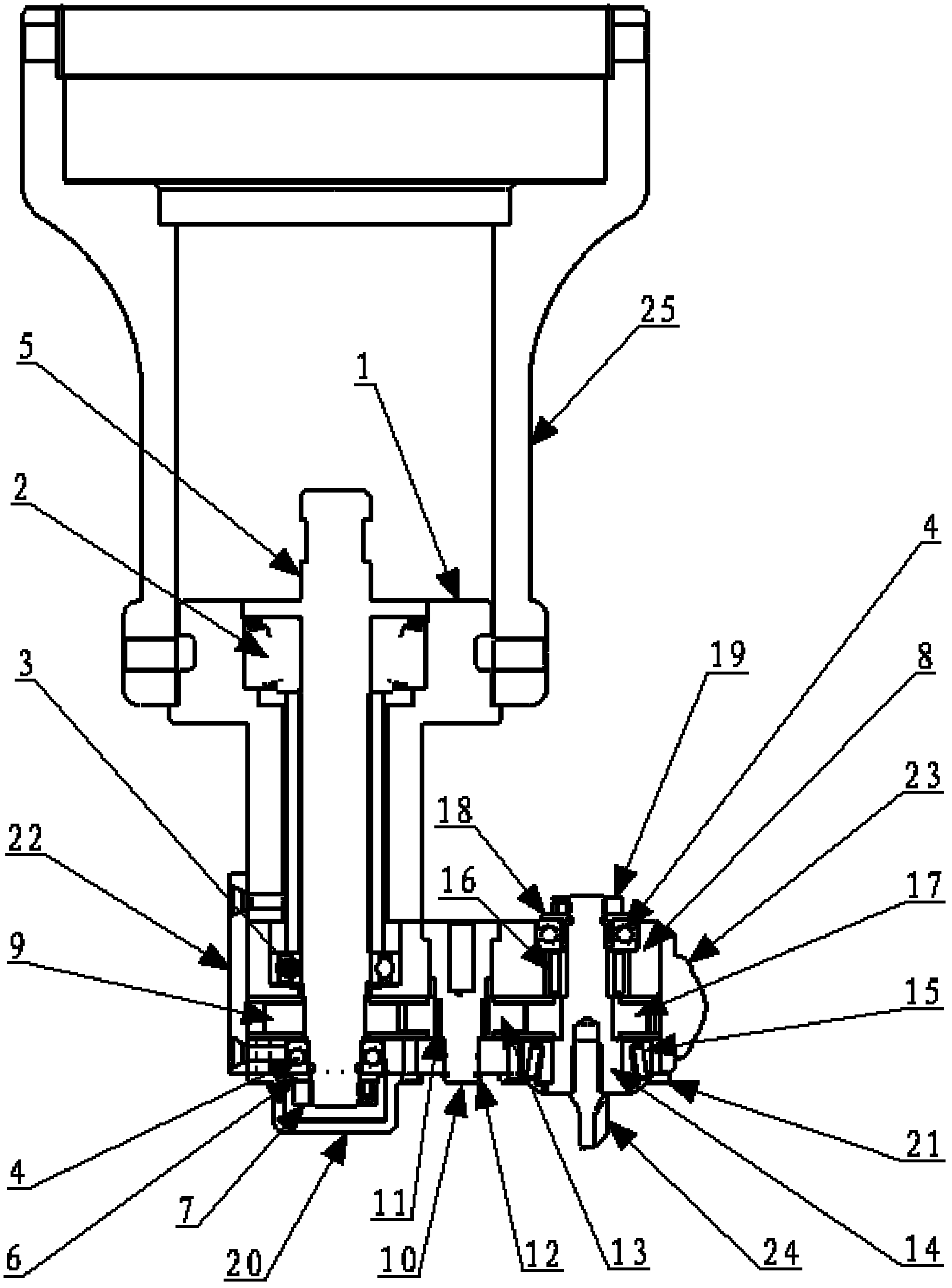
[0015] Embodiments of the present invention will be further described in detail below in conjunction with the accompanying drawings, as figure 1 Shown is a schematic structural view of the variable direction cutter provided by the embodiment of the present invention, figure 1 The variable direction cutter in the tool includes three shafts, the two ends of each shaft are fixed by bearings and nuts, each shaft is sequentially driven by gears, and fin...


PUM


Abstract

The embodiment of the invention discloses a direction-variable cutting tool. The direction-variable cutting tool comprises three shafts, wherein the two ends of each shaft are fixed through bearings and nuts; the shafts are transmitted in sequence through gears, and a milling cutter mounted on the third shaft is finally driven to rotate, so as to realize the cutting. In the product cutting and processing process, the direction-variable cutting tool is mounted and clamped in an axial Z-axis direction of a machining center of a numerical control milling machine; a housing of the direction-variable cutting tool moves synchronously with the Z-axis; the gears on the three shafts of the direction-variable cutting tool are driven to rotate through the rotation of the Z-axis; the three shafts are driven in sequence through the rotation of the gears; and the milling cutter mounted on the third shaft is finally driven to move into holes of products to cut and process the products. The cutting tool can enter into the holes to cut and process the products through variable-direction motion, so that the cutting of multi-angle inner holes by the machining center of the numerical control milling machine is improved. Therefore, cutting and processing to products are effectively improved.

Description

technical field [0001] The invention relates to the technical field of milling machine processing, in particular to a variable direction cutter. Background technique [0002] At present, in the field of mechanical manufacturing, such as CNC milling machine processing centers, commonly used tool angles are: straight shank, 45 degrees, 75 degrees and 90 degrees. However, if the CNC milling machine machining center using the above-mentioned tools encounters a half-groove product that does not penetrate the inner hole wall, these general-purpose tools are restricted and cannot perform effective cutting on this type of product, which restricts the mechanical properties of the product. Manufacturing process. Contents of the invention [0003] The purpose of the present invention is to provide a variable direction cutting tool, which can move into the hole for cutting processing by changing direction, which improves the cutting of multi-angle inner holes by the CNC milling machi...

Claims


Application Information

Patent Timeline
IPC IPC(8): B23Q5/04
Inventor 石岩峰赵国臣石峻峰倪庆祥
Owner GOALTECH
Why Eureka
Try Eureka