Feeding and discharging device for bearing outer ring machining

A bearing outer ring, intermediate position technology, applied in the direction of grinding drives, metal processing equipment, machine tools designed for grinding the rotating surface of workpieces, etc.

Pending Publication Date: 2021-03-23
JIANGSU WANDA SPECIAL BEARING CO LTD
View PDF0 Cites 0 Cited by
  • Summary
  • Abstract
  • Description
  • Claims
  • Application Information

AI Technical Summary

Problems solved by technology

[0002] In the past, when the outer ring of the bearing was processed by a grinding machine, the loading and unloading was carried out through the grinding truss loading and unloading gravity silo, and the loading and unloading device at the lower end of the truss mechanism automatically grabbed the bearing at the loading position of the grinding truss loading and unloading gravity silo The outer ring is sent to the grinding machine to grind the raceway with the grinding wheel. After the grinding is completed, the outer ring of the ground bearing is picked up by the loading and unloading device at the lower end of the truss mechanism and sent to the grinding truss loading and unloading gravity bin. position, to complete the processing; in the past, for the outer ring of the inner single-rib straight raceway bearing or the outer ring of the small-sized double-rib straight raceway bearing, the loading and unloading device of the bearing outer ring is currently using the upper jaw and the Lower jaw mechanism, the upper jaw is a fixed plate and installed on the lower side of the cylinder, the lower jaw is a round rod and installed on the telescopic end of the cylinder, the upper jaw and the lower jaw cooperate to clamp the outer ring of the bearing ; When clamping the outer ring of a straight raceway bearing with a single rib, the round rod extends from the inner side of the outer ring of the bearing without the annular rib. The annular rib will not affect the clamping of the round rod and the upper jaw. When the outer ring of the bearing is inserted into the middle position of the bearing outer ring, the outer ring of the bearing will not be deflected on one side; The inner side of the two annular ribs, so that there will be no deflection problem when the outer ring of the double rib straight raceway bearing is clamped; however, the round rod needs to be lengthened when the outer ring of the double rib straight raceway bearing is clamped to It happens to be hooked on the inside of the two annular ribs inside the outer ring of the bearing, so that there will be no deflection problem. However, because it is a large-scale bearing outer ring, the space for the clamping position in the center of the grinding machine is fixed, and there is not much space for it. The round rod is pulled out from the outer ring of the bearing, and the grinding wheel mechanism interferes behind it, so the extension of the round rod cannot meet the clamping use of the outer ring of the large-scale double rib straight raceway bearing. If the round rod is not lengthened, the round rod will only hook when hooking. The ring rib on one side will cause the outer ring of the bearing to deflect, which will deflect when clamping, and the position will not be correct when feeding, and the subsequent automatic processing will not meet the requirements at all.

Method used


Image

  • Feeding and discharging device for bearing outer ring machining
  • Feeding and discharging device for bearing outer ring machining
  • Feeding and discharging device for bearing outer ring machining

Examples


Embodiment Construction

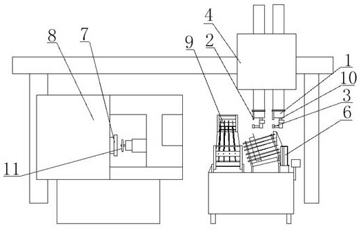
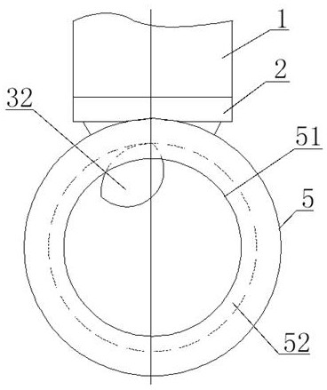
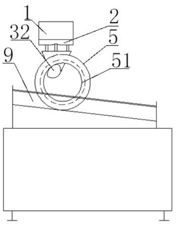
[0024] Refer to attached Figure 1-6 , a loading and unloading device 10 for bearing outer ring processing, which includes a cylinder 1, an upper jaw 2 and a lower jaw 3, the telescopic end of the cylinder 1 is installed downward on the lower end of the telescopic cantilever of the truss mechanism 4, and the cylinder 1 A lower jaw 3 is installed at the telescopic end below, and an upper jaw 2 is installed at a position close to one side below the cylinder 1. The lower jaw 3 includes a round rod 31 and a cam block 32, and one end of the round rod 31 is horizontally installed on the side of the cylinder 1. One side of the telescopic end, the other end of the round rod 31 is equipped with a cam block 32, the arc of the upward arc surface 33 of the cam block 32 is less than or equal to the inner diameter arc of the bearing outer ring 5, the outer side of the round rod 31 and the cam block The inner side of the arc surface 33 of 32 is tangent, when the lower jaw 3 is installed, one...


PUM


Abstract

The invention relates to a feeding and discharging device for bearing outer ring machining. The feeding and discharging device comprises an air cylinder, an upper clamping jaw and a lower clamping jaw, the telescopic end of the air cylinder is downwards installed at the lower end of a telescopic cantilever of a truss mechanism, the lower clamping jaw is installed at the telescopic end of the lowerportion of the air cylinder, the upper clamping jaw is installed at the position, close to one side, of the lower portion of the air cylinder, the lower clamping jaw comprises a round rod and a cam block, one end of the round rod is horizontally installed on one side of the telescopic end of the air cylinder, and the cam block is installed at the other end of the round rod. The feeding and discharging device has the advantages that the cam block is designed at one end of the round rod, the cam block meets the requirements that when a large double-flange straight raceway bearing outer ring isclamped, the highest point of the cam block abuts against the middle of the inner side of the bearing outer ring, the bearing outer ring cannot incline in the hooking process, and the bearing outer ring cannot deflect when clamped to the upper clamping jaw finally, and the subsequent machining requirements of a grinding machine are met; and the original gravity rolling discharging mode cannot be met due to the design of the cam block, however, through the arc-shaped surface design and the installation position of the cam block, it is ensured that effective discharging can be achieved even if the front end of the round rod tilts, and the cam block cannot interfere with an annular catch of the bearing outer ring during discharging.

Description

technical field [0001] The invention relates to the field of bearing outer ring processing, in particular to a loading and unloading device for bearing outer ring processing. Background technique [0002] In the past, when the outer ring of the bearing was processed by a grinding machine, the loading and unloading was carried out through the grinding truss loading and unloading gravity silo, and the loading and unloading device at the lower end of the truss mechanism automatically grabbed the bearing at the loading position of the grinding truss loading and unloading gravity silo The outer ring is sent to the grinding machine to grind the raceway with the grinding wheel. After the grinding is completed, the outer ring of the ground bearing is picked up by the loading and unloading device at the lower end of the truss mechanism and sent to the grinding truss loading and unloading gravity bin. position, to complete the processing; in the past, for the outer ring of the inner s...

Claims


Application Information

Patent Timeline
Patent Type & Authority Applications(China)
IPC IPC(8): B24B5/35B24B5/36B24B41/04B24B41/06B24B47/20B24B47/22
CPCB24B5/35B24B5/355B24B5/36B24B41/04B24B41/06B24B47/20B24B47/22
Inventor 何敏
Owner JIANGSU WANDA SPECIAL BEARING CO LTD
Why Eureka
Try Eureka