Combined fixture used for fixing optical fiber stress rod

A technology of optical fiber stress and combined fixture, which is applied in the direction of grinding workpiece brackets, etc., can solve problems such as difficulty in ensuring circular symmetry, deviation of the concentricity of optical fiber stress rods, and affecting the quality of optical fibers, etc., to achieve the goal of overcoming excessive dependence and good circular symmetry Effect

Active Publication Date: 2012-06-27
武汉长盈通光电技术股份有限公司
View PDF4 Cites 7 Cited by
  • Summary
  • Abstract
  • Description
  • Claims
  • Application Information

AI Technical Summary

Problems solved by technology

However, using a tapered sleeve top to fix the fiber stress rod is only suitable for fiber stress rods with a single diameter and a relatively regular tapered end. In the actual production process, fiber stress rods with various diameters will be encountered, and most optical fib

Method used


Image

  • Combined fixture used for fixing optical fiber stress rod
  • Combined fixture used for fixing optical fiber stress rod
  • Combined fixture used for fixing optical fiber stress rod

Examples


Embodiment Construction

[0024] Specific embodiments of the present invention will be described in further detail below in conjunction with the accompanying drawings.

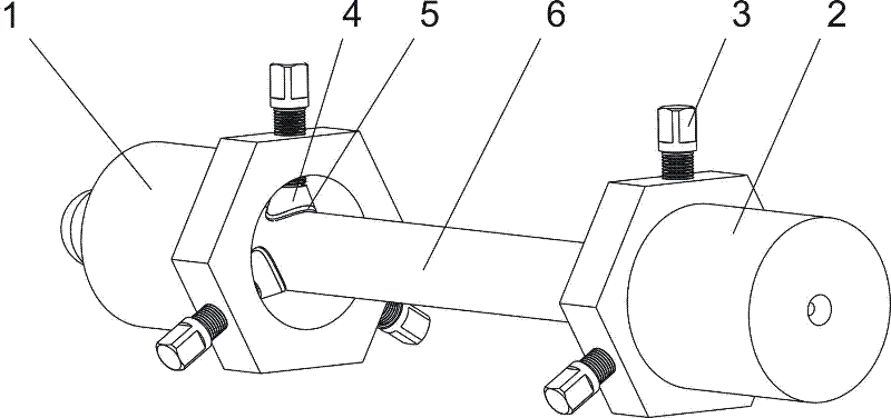
[0025] Such as figure 1 As shown, a combined clamp for fixing optical fiber stress rods of the present invention includes left fasteners 1 and right fasteners 2 for clamping both sides of optical fiber stress rods 6, and six sets of helical columns 3, clamping heads 4 and Gasket 5, specifically as follows.

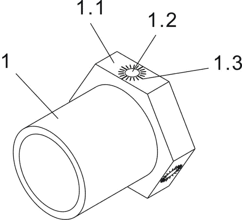
[0026] Such as figure 2 As shown, the left fixture 1 is hollow and cylindrical, and the outer surface of the left fixture 1 side is provided with a regular hexagonal flange 1.1, and the flange 1.1 is evenly provided with three radial screw holes 1.2, which are used to install the screw column 3 .

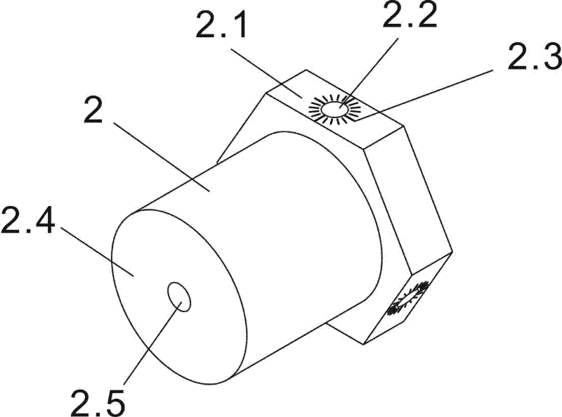
[0027] Such as image 3 and Figure 4 As shown, the right fixture 2 is cylindrical with one end closed, and the outer surface of the right fixture 2 side is provided with a flange 2.1, and the flange 2.1 is evenly provided with thr...


PUM

PropertyMeasurementUnit
Thicknessaaaaaaaaaa

Abstract

The invention relates to a combined fixture used for fixing an optical fiber stress rod. The combined fixture comprises a left fixing component and a right fixing component which are respectively used for clamping two sides of an optical fiber stress rod, wherein the left fixing component is of a hollow tubular shape, the outer surface of the left fixing component is provided with a flange, the flange is provided with a plurality of radial screw holes, each screw hole is internally provided with a screw pile which is provided with a clamping head and is connected with the screw hole by virtue of a screw thread, and the a screw pile is used for clamping one side of the optical fiber stress rod to be processed; one end of the right fixing component is of a closed tubular shape, the outer surface of the right fixing component is provided with a flange, the flange is provided with a plurality of radial screw holes, each screw hole is internally provided with a screw pile which is provided with a clamping head and is connected with the screw hole by virtue of a screw thread, and the clamping head is used for clamping the other side of the optical fiber stress rod to be processed; and a center hole is arranged at the center of the closed end of the right fixing component and is used for being matched with a center of grinding equipment, thus the whole fixture and the rotating shaft of the grinding equipment are coaxial. The combined fixture provided by the invention overcomes the defect that a clamping mechanism is very dependent on cone-shaped end of the optical fiber stress rod in the traditional scheme, and an optical fiber stress rod obtained by grinding has good circular symmetry.

Description

technical field [0001] The invention relates to the processing of optical fiber stress rods during the preparation process of polarization-maintaining optical fibers, in particular to a combination fixture for fixing optical fiber stress rods. Background technique [0002] Optical fiber stress rods are one of the important materials used to manufacture optical fibers. Taking the manufacturing process of Panda-type polarization-maintaining optical fiber as an example, it first uses PCVD to manufacture optical fiber preforms and high-concentration boron-doped stress rods respectively; then uses quartz deep hole technology to punch two pre-designed symmetrical circular holes in the optical fiber preforms , and then insert the boron-doped stress rod into the perforated optical fiber preform to form a panda-shaped polarization-maintaining optical fiber preform; finally, the panda-shaped polarization-maintaining optical fiber preform is drawn through a drawing tower to obtain a pa...

Claims


Application Information

Patent Timeline
IPC IPC(8): B24B41/06
Inventor 谢利华郭伟华汪洪海皮亚斌
Owner 武汉长盈通光电技术股份有限公司
Why Eureka
Try Eureka