Two-wheeled self-balancing electrombile
A technology of self-balancing electric vehicles and electric motors, which is applied to motor vehicles, bicycles, and foldable bicycles. It can solve problems such as lack of support points, difficulty in moving the car stably, and difficulty in stabilizing the ankle and knee joints. The effect of stability
- Summary
- Abstract
- Description
- Claims
- Application Information
AI Technical Summary
Problems solved by technology
Method used
Image

Examples
Embodiment Construction
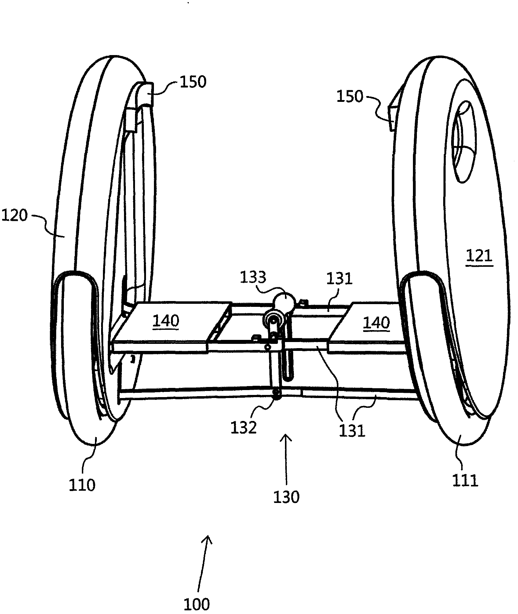
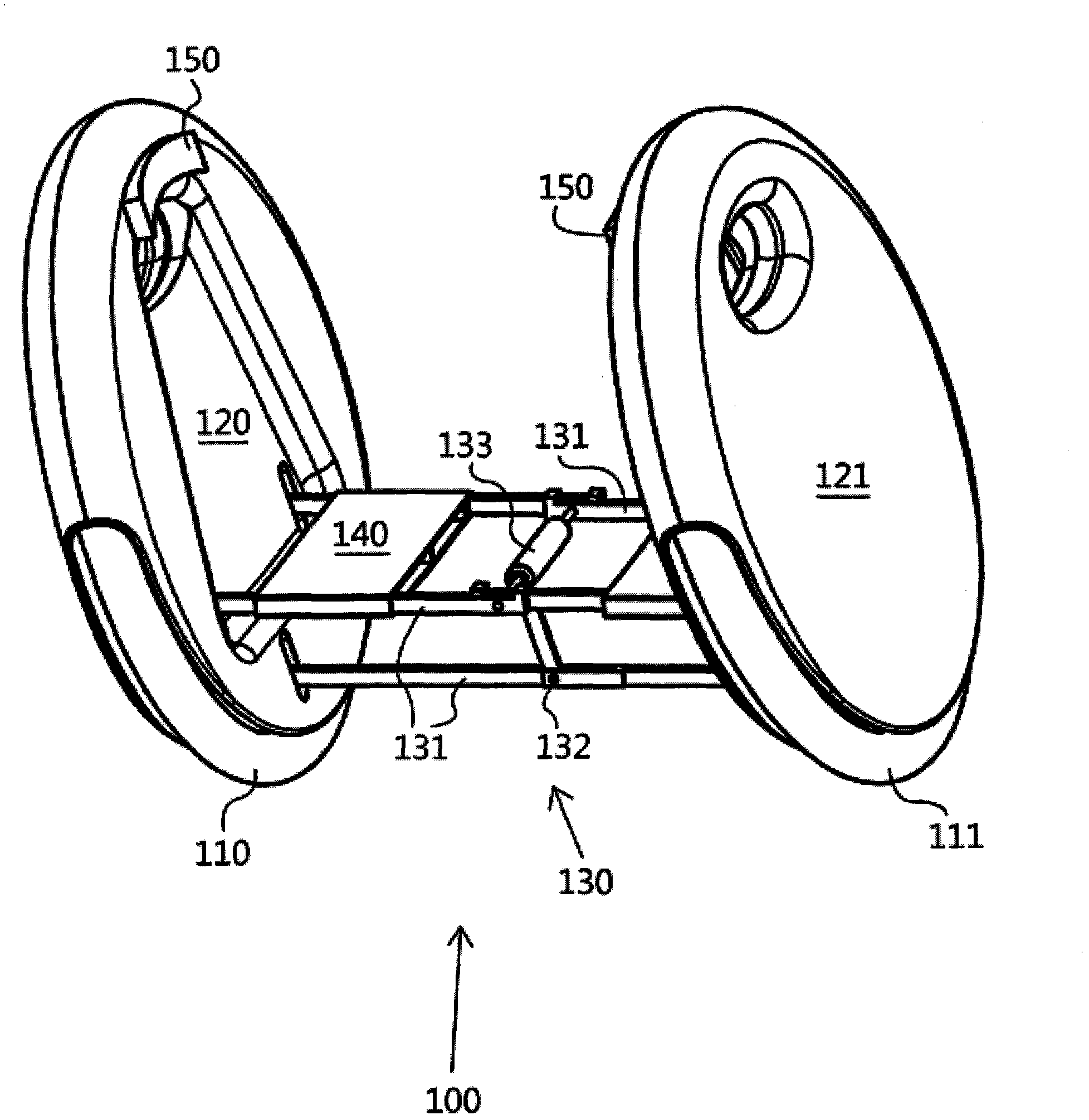
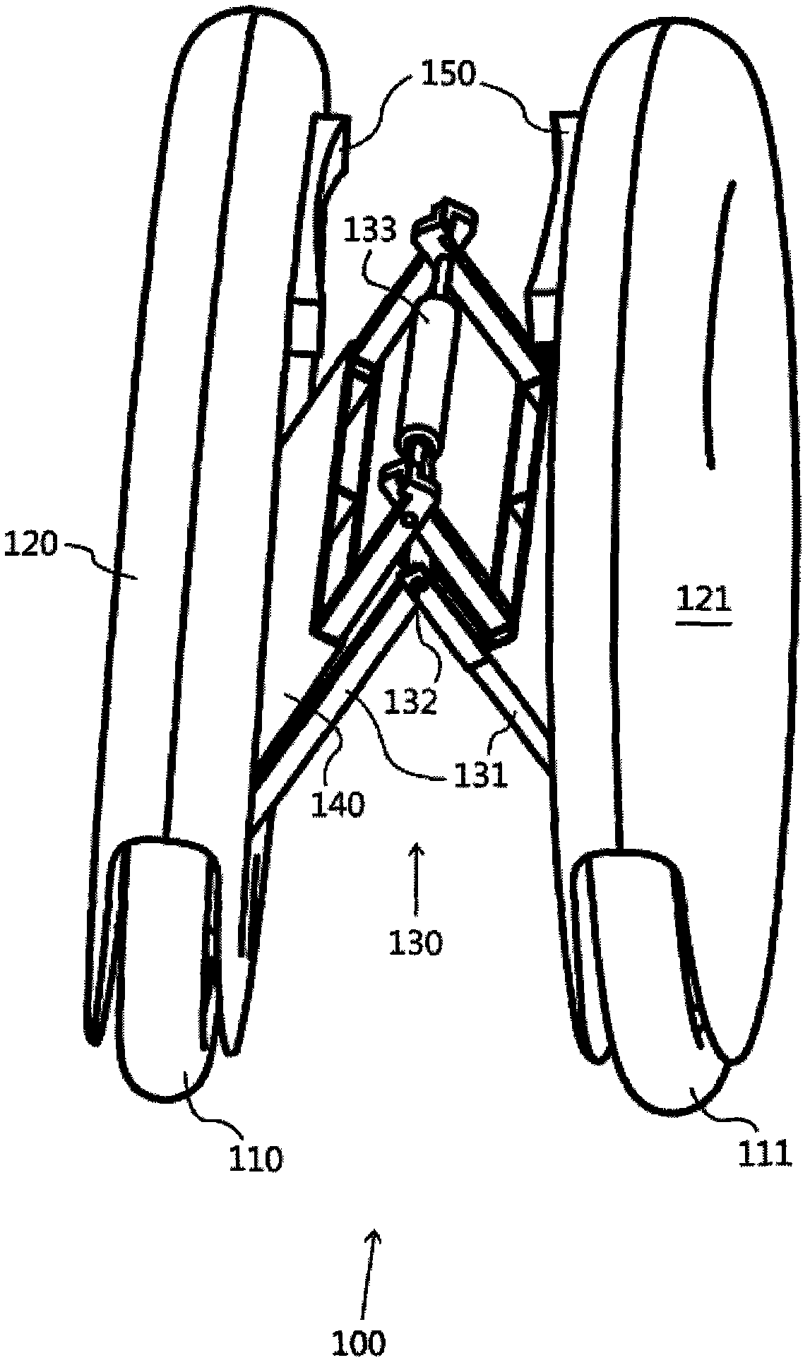
[0019] refer to figure 1 , which is a side perspective view of the embodiment of a two-wheeled self-balancing electric vehicle proposed by the present invention. The composition of the two-wheeled self-balancing electric vehicle 100 in the figure includes: two wheels, a first wheel 110 and a second wheel 111; two wheel frames, a first wheel frame 120 and a second wheel frame 121; The wheel frame is connected; a connecting mechanism 130, one end of which is connected with the first wheel frame 120, and the other end is connected with the second wheel frame 121; two pedals 140, which are located between the two wheels 110 and 111, they It is used for standing on both feet of the cyclist; and a handle 133, which is connected to the connection mechanism 130, is used to carry the electric vehicle 100. 132 on the figure is a hinge, and 150 is a leg board, which will be described hereinafter.
[0020] The wheels 110 and 111 are arranged side by side, mirror-symmetrical to each othe...
PUM
 Abstract
Description
Claims
Application Information
 - Generate Ideas
- Intellectual Property
- Life Sciences
- Materials
- Tech Scout
- Unparalleled Data Quality
- Higher Quality Content
- 60% Fewer Hallucinations
Browse by: Latest US Patents, China's latest patents, Technical Efficacy Thesaurus, Application Domain, Technology Topic, Popular Technical Reports.
© 2025 PatSnap. All rights reserved.Legal|Privacy policy|Modern Slavery Act Transparency Statement|Sitemap|About US| Contact US: help@patsnap.com