Roof regeneration medium-length hole ore blast backfill mining method

A backfill mining method and roof technology, which are applied in the fields of backfill, ground mining, mining equipment, etc., can solve the problems of difficult implementation of roof protection technology, high cutting ratio per thousand tons, high cost, and achieve safe and reliable mining environment. The effect of dilution control and production cost reduction

Active Publication Date: 2012-06-27
CENT SOUTH UNIV
View PDF4 Cites 31 Cited by
  • Summary
  • Abstract
  • Description
  • Claims
  • Application Information

AI Technical Summary

Problems solved by technology

The outstanding problems of the former are that the large amount of mining and cutting works and the high ratio of mining and cutting per 1,000 tons lead to high mining costs, and workers spend a lot of time on leak prevention, resulting in too long time for panel mining and increased labor intensity; When the chassis is unstable, it is difficult to form a stable funnel on the chassis. If the funnel is moved up to the ore body, the loss of dilution will be greatly increased.
The main problems of the latter are that the process is complicated, the implementation of safe and reliable roof protection technology is difficult, the cost is high, and the effect is not ideal. In the case of large changes in ore grade, it is inconvenient to carry out separate mining.
Therefore, the broken roof and floor become the bottleneck that restricts the safe, efficient and low-cost mining of this type of ore body

Method used


Image

  • Roof regeneration medium-length hole ore blast backfill mining method
  • Roof regeneration medium-length hole ore blast backfill mining method
  • Roof regeneration medium-length hole ore blast backfill mining method

Examples


Embodiment Construction

[0023] The present invention will be further elaborated below in conjunction with accompanying drawing:

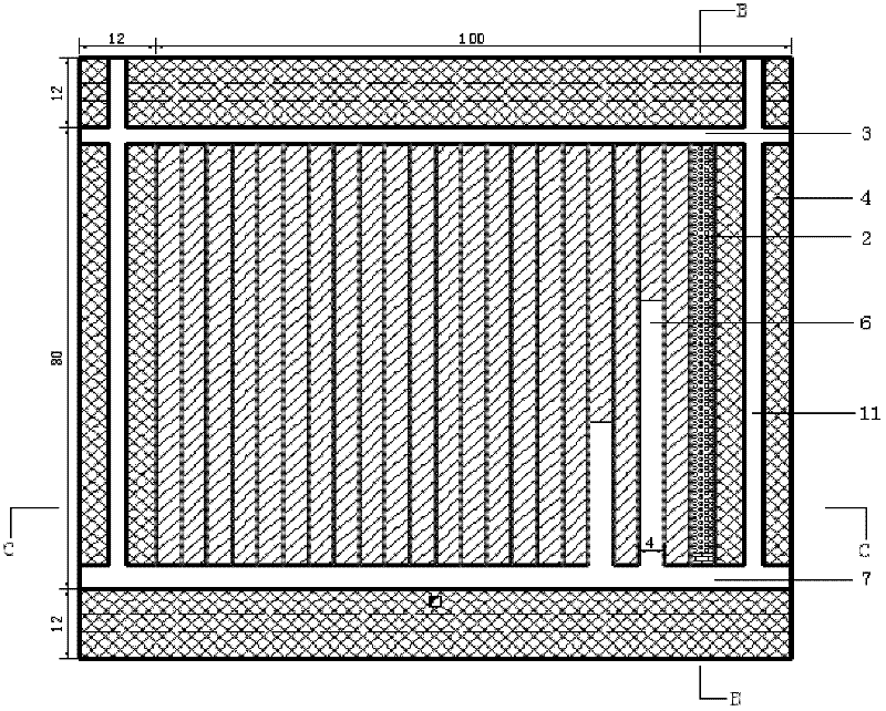
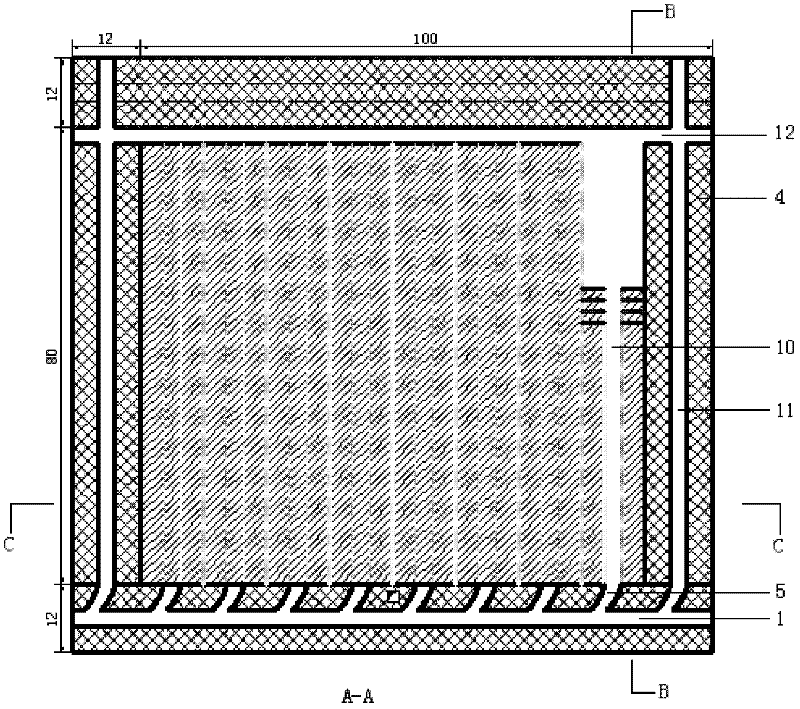
[0024] (1) Divide the ore body into the middle section, leave a 12m continuous ore pillar along the trend in the middle, and then divide the ore body into panels through the inter-panel pillar 4 along the dip. The inter-panel pillar 4 is 12m wide and 80m long along the dip. The strike length is 100m, and the panel area is divided into several stopes along the strike;

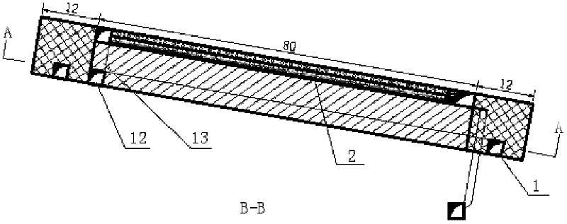
[0025] (2) Arrange the main access road 1 of the scraper along the strike at the bottom plate of the continuous ore pillar, with a size of 3m×3m, communicate with each stope through the stope connecting road 5, and communicate with the ramp at one end of the ore body; 4 The position of the bottom plate is arranged along the inclination of the branch route 11 of the scraper, with a size of 3m×3m, which is used as a channel to communicate with each middle section; at the position of the top plate at the upper ...


PUM


Abstract

The invention discloses a roof regeneration medium-length hole ore blast backfill mining method, which comprises the following steps of: dividing an ore body into middle sections, reserving continuous ore pillars in the middle along the advancing direction, dividing the ore body into a panel through panel barriers along the tilt direction, and laying out a plurality of stopes in the panel along the advancing direction; arranging a scraper main access road on a base plate of the continuous ore pillars along the advancing direction, using the scraper main access road as a communicating channel to communicate with various topes, arranging a scraper branch access road on a base plate of the panel barriers along the tilt direction, and using the scraper branch access road as a channel to communicate with various middle sections; and stoping an upper layer and a lower layer integrally divided in the panel, namely stoping the ore body in the upper layer, performing waste stone cemented filling to obtain an artificial roof, performing high-efficiency medium-length hole ore blast on the ore body in the lower layer, removing ore by using a scraper, making the ore pass through a stope chute to descend to a panel haulage roadway, and loading and conveying the ore on an underground electric locomotive. By the method, a safe stoping environment is recreated, a high-efficiency mining process is implemented, a preliminary mining process is simple, operation interference between the upper and lower layers is small, the loss and dilution are effectively controlled, and the production cost is greatly reduced.

Description

technical field [0001] The present invention relates to a mining method, in particular to a method of roof reconstruction in deep holes followed by filling and mining, which is mainly applicable to the gentle slope where the roof and floor of the ore body are broken, the ore body is stable, the ore grade is high, and the ground surface does not allow caving. Medium-thick ore body. Background technique [0002] The gently inclined medium-thick ore body with unstable roof and floor has always been recognized by the mining industry as a difficult-to-mining ore body. For the mining of this type of ore body, the traditional methods mainly include the chassis funnel segmented empty field method and the advanced roof cutting method. The effect has not been very satisfactory, and the safe, efficient and low-cost mining of this type of ore body cannot be realized. The production practice of many domestic mines shows that these methods have shortcomings to varying degrees. The outst...

Claims


Application Information

Patent Timeline
Patent Type & Authority Applications(China)
IPC IPC(8): E21C41/16E21F15/00
Inventor 邓红卫周科平胡普仑杨念哥高峰翟建波张亚明雷涛
Owner CENT SOUTH UNIV
Why Eureka
Try Eureka