Rod end joint bearing

A rod end joint bearing and rod end technology, applied in the field of mechanical parts, can solve problems such as short gap life, achieve product quality improvement, novel structure, and increase the effect of use

Inactive Publication Date: 2012-06-27
天津市宝坻区东亚光大地毯厂
View PDF10 Cites 1 Cited by
  • Summary
  • Abstract
  • Description
  • Claims
  • Application Information

AI Technical Summary

Problems solved by technology

[0002] At present, rod end joint bearings mainly include: rod end shell, self-lubricating pad, and perforated ball. Because the contact surface between the perforated ball and the

Method used


Image

  • Rod end joint bearing
  • Rod end joint bearing

Examples


Example Embodiment

[0013] Example 1

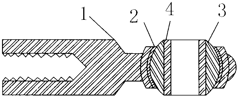
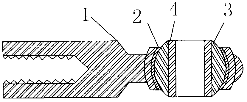
[0014] Such as figure 1 As shown, a rod end joint bearing includes a rod end housing 1, a self-lubricating cushion layer 2, a perforated ball 3, and a perforated shaft 4, wherein the perforated ball 3 is arranged in the rod end housing 1, and the self-lubricating The lubricating cushion layer 2 is arranged between the perforated ball 3 and the rod end housing 1, and the perforated shaft 4 is arranged in the hole of the perforated ball 3.

[0015] In the rod end joint bearing of the present invention, the perforated shaft 4 is arranged in the hole of the perforated ball 3, the perforated shaft 4 is in clearance fit with the inner hole of the perforated ball 3, and the perforated shaft 4 is in full contact with the inner hole of the perforated ball 3. When the rotation speed is increased, the perforated ball 3 and the rod end housing 1 only play a guiding role.

[0016] When the rod end joint bearing of the present invention is applied, it is only necessary to dire...


PUM


Abstract

Belonging to the field of mechanical parts, the invention relates to a rod end joint bearing, which comprises a rod end shell, a self-lubricating cushion layer, a perforated ball, and a perforated shaft, wherein, the self-lubricating cushion layer, the perforated ball, and the perforated shaft are arranged on the rod end shell. Compared with prior art, the invention has the advantages of novel structure and simple operation, and only a rod end joint bearing of the same model needs to be replaced directly. The perforated shaft and the inner hole of the perforated ball are in full contact, so that the rotation speed and the service life are enhanced, and its application is increased. Therefore, the product quality can be substantially improved.

Description

Technical field [0001] The invention relates to a rod end joint bearing, which belongs to the field of mechanical parts. Background technique [0002] At present, rod end joint bearings mainly include: rod end shell, self-lubricating cushion, perforated ball, because the contact surface between the perforated ball and the rod end shell is too small, there is a self-lubricating cushion in the middle, which will last for a period of time under fast operation. The gap life is too short. Summary of the invention [0003] The purpose of the present invention is to solve the above-mentioned problems and provide a rod end joint bearing, which improves the durability of the rod end joint bearing and increases the usage, thereby improving the product quality. [0004] The technical solution of the present invention is to provide a rod end joint bearing, which includes a rod end shell, a self-lubricating cushion, a perforated ball, and a perforated shaft, wherein the self-lubricating cushion...

Claims


Application Information

Patent Timeline
IPC IPC(8): F16C23/04
Inventor 孙庆杰
Owner 天津市宝坻区东亚光大地毯厂
Why Eureka
Try Eureka