Electric brake and automobile

A technology of electric brakes and electromagnetic clutches, applied in the direction of brake actuators, gear transmission mechanisms, mechanical equipment, etc., can solve the problem of long time for motor transmission torque to generate brake clamping force, which cannot meet the requirements of brake response time, Poor real-time braking effect and other problems, to achieve good braking effect, compact structure, and shorten the response time

Active Publication Date: 2012-06-27
CHERY AUTOMOBILE CO LTD
View PDF6 Cites 16 Cited by
  • Summary
  • Abstract
  • Description
  • Claims
  • Application Information

AI Technical Summary

Problems solved by technology

During the above-mentioned braking process, due to the longer time for the motor to transmit the torque to generate the braking clamping force, the real-time performance of the braking effect is poor, which cannot meet the requirements for the br

Method used


Image

  • Electric brake and automobile
  • Electric brake and automobile
  • Electric brake and automobile

Examples


Embodiment 1

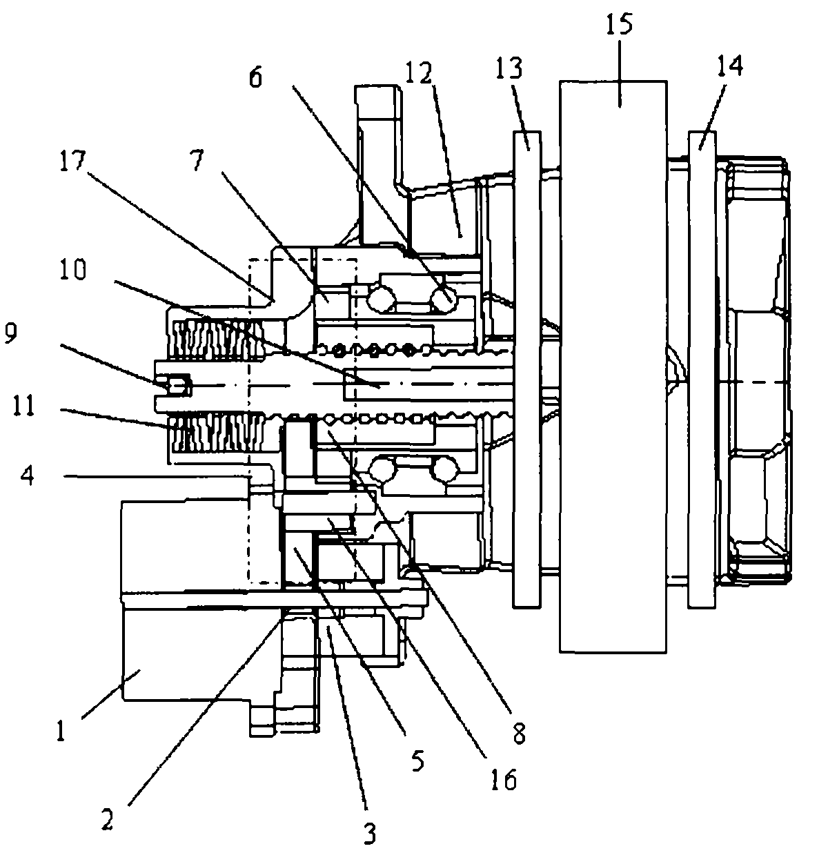
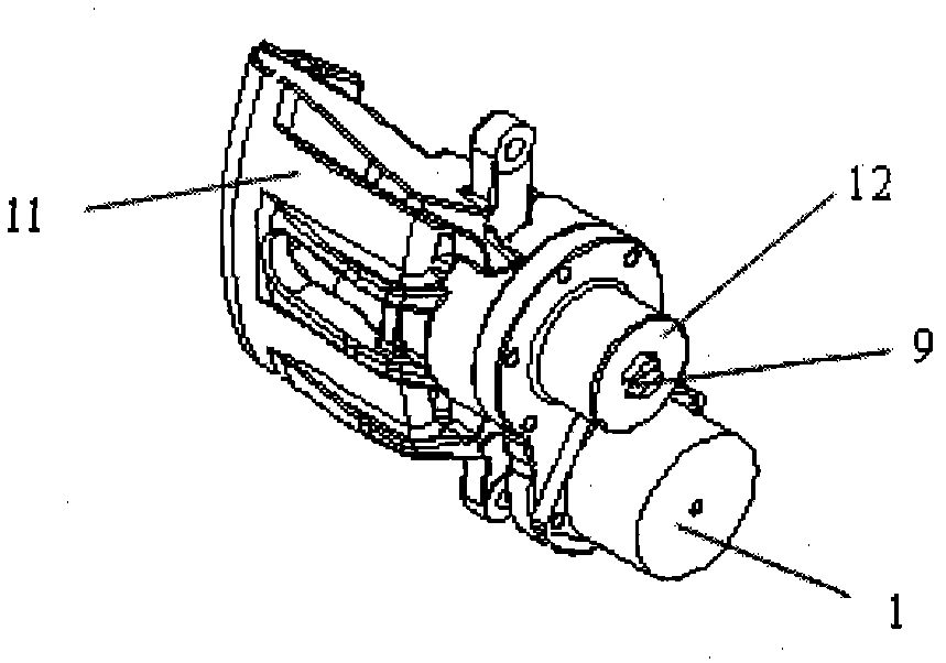
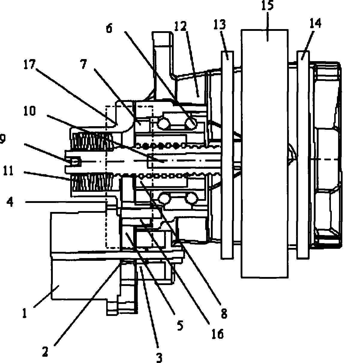
[0024] Such as figure 1 , 2 As shown, in this embodiment, the electric brake includes a housing 17, a brake disc 15, brake pads 13, 14, a floating caliper 12, a power mechanism, a pressure maintaining mechanism, and an energy storage mechanism. The power mechanism includes a motor 1, a torque amplification mechanism and a motion mechanism, the torque amplification mechanism is arranged between the motor 1 and the motion mechanism, the input end of the torque amplification mechanism is connected with the output shaft of the motor 1, Its output end is connected with the motion mechanism.

[0025] In this embodiment, the moving mechanism is arranged in the housing 17, and the moving mechanism adopts a non-self-locking screw mechanism, and the screw mechanism includes a ball screw shaft 10, a screw nut 8, a ball bearing 6, and a limiter. bit agency9. The screw nut 8 is set on the ball screw shaft 10, the inner side of the ball bearing 6 is riveted with the screw nut 8, the oute...

Embodiment 2

[0035] The difference between this embodiment and Embodiment 1 is that there is no energy storage mechanism.

[0036] Other structures and uses in this embodiment are the same as those in Embodiment 1, and will not be repeated here.


PUM


Abstract

The invention provides an electric brake, comprising a shell (17), a brake disc (15), a brake block and a power mechanism which can push the brake block to move forwards so as to clamp the brake disc, wherein the power mechanism comprises a motor (1) and a movement mechanism which is connected with an output end of the motor, the movement mechanism can transform the rotating movement of the motor into straight line movement, and the brake block is arranged in front of the movement mechanism. The electric brake is characterized in that: the power mechanism also comprises a torque amplification mechanism which is arranged between the motor and the movement mechanism, an input end of the torque amplification mechanism is connected with the output end of the motor, and an output end of the torque amplification mechanism is connected with the movement mechanism. The electric brake is compact in structure, is short in brake response time and can generate greater brake clamping force.

Description

technical field [0001] The invention belongs to the technical field of automobile manufacturing, and in particular relates to an electric brake and an automobile using the electric brake. Background technique [0002] At present, most vehicle braking systems at home and abroad still use hydraulic braking systems based on hydraulically controlled mechanical pressure to achieve braking purposes. The traditional hydraulic braking system controls the braking force through solenoid valves (including booster valves, pressure relief valves, etc.). The above-mentioned hydraulic braking system has defects such as complex structure, inconvenient installation, high price, failure to monitor faults in real time, and slow braking response. [0003] The new electromechanical braking system has just started. It simulates the pedal force feeling through the pedal feeling simulator, collects the pedal displacement through the pedal displacement sensor, and obtains the output braking torque ...

Claims


Application Information

Patent Timeline
IPC IPC(8): F16D65/18F16D121/24F16D125/20
Inventor 王陆林高国兴
Owner CHERY AUTOMOBILE CO LTD
Why Eureka
Try Eureka