
Waveform reconstructor for optical disk read channel

a read channel and waveform reconstruction technology, applied in the field of readout systems, can solve the problems of limiting the overall through-put of the data storage system, affecting the bandwidth or stability of the readout system, and requiring additional coordination, so as to avoid the undesirable characteristics of the system

Inactive Publication Date: 2007-05-03
PLASMON LMS
View PDF17 Cites 8 Cited by
  • Summary
  • Abstract
  • Description
  • Claims
  • Application Information

AI Technical Summary

Benefits of technology

[0008] The present invention provides a readout system which creates a synchronous read signal from quasi-synchronous sample data. By utilizing this methodology, PLLs can effectively be eliminated from the readout system, thus eliminating the problems associated with increasing signal processing delays and helping to increase the bandwidth.
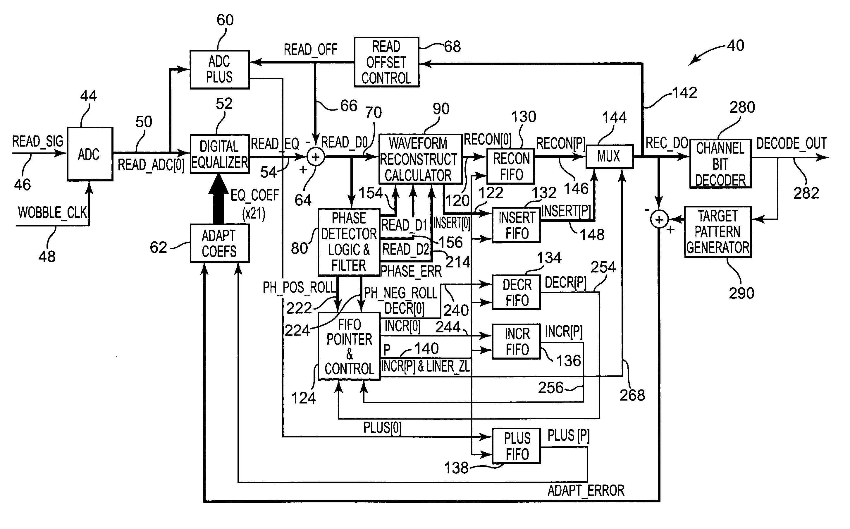
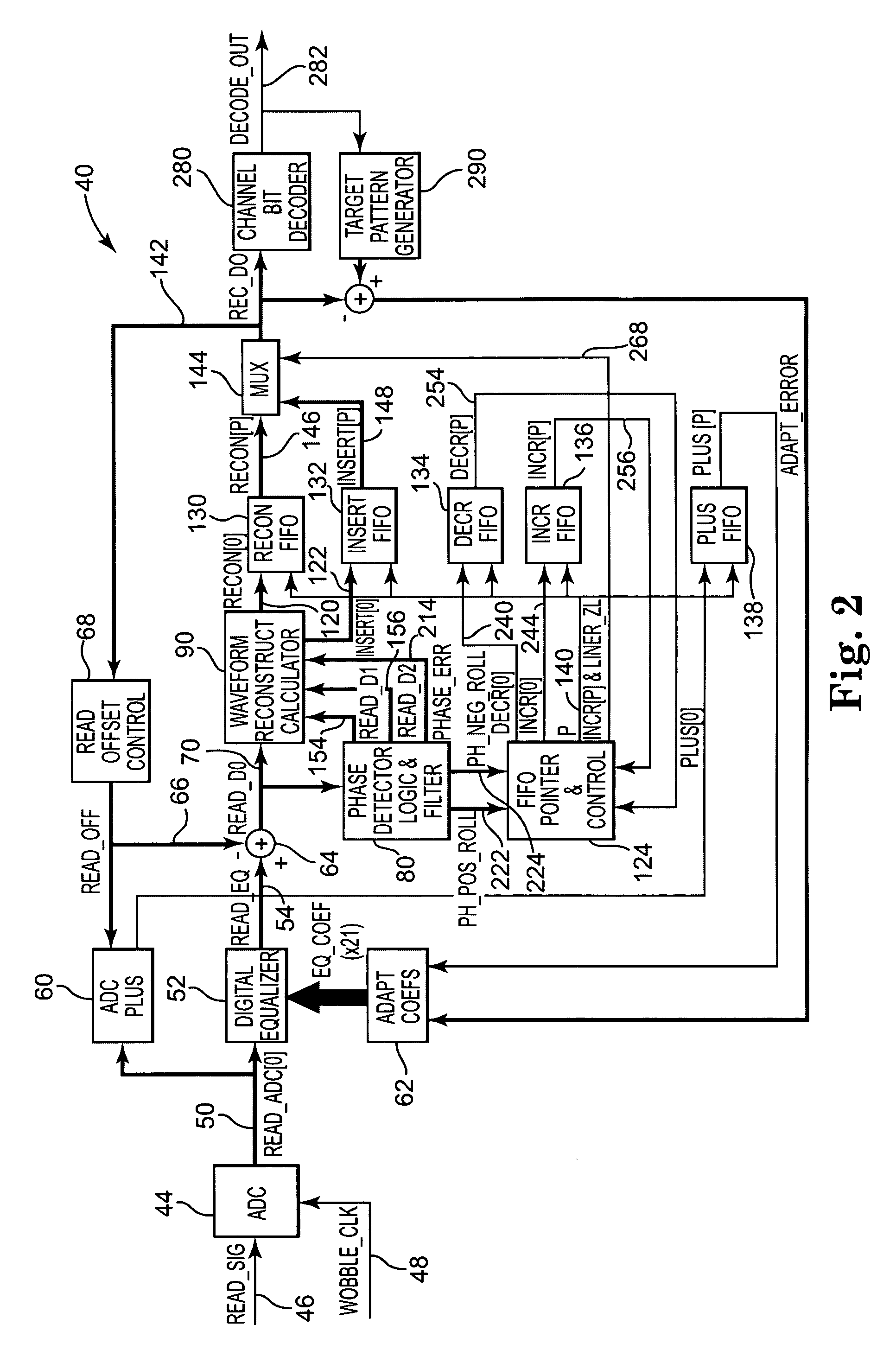
[0009] Generally speaking, the readout system of the present invention reconstructs the waveform to provide a sample that is equivalent to one which would have been sampled at precisely the right time. This avoids delays in timing issues inherent in existing readout systems, and again increases bandwidth. Further, the system of the present invention allows for the use of additional systems that provide conditioning and / or corrections desired. For example, the present invention can utilize an equalizer and other signal conditioning components to provide additional accuracy. This use of an equalizer provides compensation for many different things, such as defocus, disk tilts, cover layer deficiencies, and other undesirable optical effects.
[0014] The output from the equalizer is provided to a specialized phase detector which calculates a phase error based on an anticipated signal characteristic. In addition, the specialized phase detector also calculates an estimated phase error at each midpoint, which is one half of the system channel bit. In order to achieve both calculations (phase error and midpoint phase error), first and second derivatives are utilized in the analysis to provide further accuracy. The use of these more comprehensive signal processing components allows for a more accurate phase error measurement and subsequent recreation of the waveform.
[0017] As mentioned, the present invention further includes a waveform reconstructor which receives both readout samples from the equalizer, and phase error signals from the specialized phase detector. The waveform reconstructor then calculates a reconstructed sample value based on these inputs. By accomplishing this reconstruction in this way, the waveform reconstructor can adjust for phase errors in its calculation. Additionally, the waveform reconstructor calculates an insert sample. This insert sample is of a value that would be appropriate if insertion is required. Both the reconstructed sample and the insertion sample are provided to a reconstruction register and an insert register respectively. These registers also receive control signals from the register pointer / control system of the present invention. Additional registers included in the system are utilized to track synchronization of equalizer and insert operations. All of these registers are identical and controlled by the same register pointer and control system.
[0018] At an output stage of the present invention, a multiplexer is utilized to receive both the reconstructed and the insert sample. Based upon a control signal from the register pointer / control mechanism, either the appropriate reconstructed sample or insert sample is output to a channel bit decoder. The output is also provided to a read offset control for use in monitoring read offsets. Naturally, the channel bit decoder provides an output to subsequent systems which provides for effective decoding of the marks and spaces saved on the disk.
[0021] As evident from the discussion above, the present invention is configured and designed to specifically provide a read channel with high bandwidth capable of accommodating data rates required by today's systems. Further, the system is set up and specifically designed to provide a synchronous read signal from a quasi-synchronous data sample. This feature allows for the elimination of a classic phase lock loop, thus avoiding the undesirable characteristics of those systems.

Problems solved by technology

Data storage systems also often include error correcting capability, which obviously requires additional coordination.
However, the delays incorporated in the PLL can detrimentally affect the bandwidth or stability of the readout system.
That is, delays of traditional phase lock loops have limited the bandwidth, thus limiting the overall through-put from the data storage system.
In addition, these systems typically require additional data overhead (longer VFO field) to allow for the PLL to become locked.
Additionally, phase errors are often created by phase lock loops which also must be dealt with.
Optical effects also have many detrimental results which can distort the signals causing detrimental effects to the system.
Typical corrective efforts to deal with these optical effects (e.g., equalizers and related conditioning circuitry) can also create delays in the PLL based readout system.

Method used


Image

  • Waveform reconstructor for optical disk read channel
  • Waveform reconstructor for optical disk read channel
  • Waveform reconstructor for optical disk read channel

Examples


Embodiment Construction

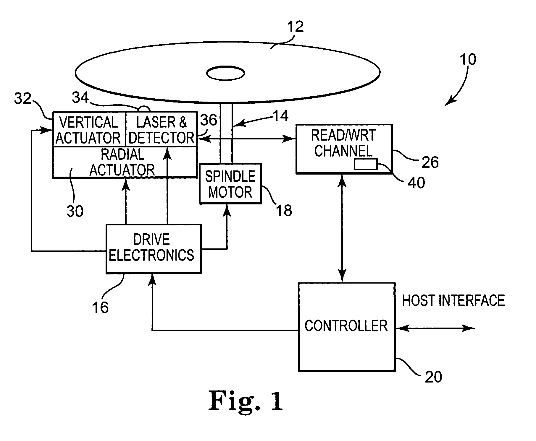
[0031] The present invention relates to a readout system used within a data storage device. While the data storage device can take many forms, one exemplary system is shown in FIG. 1. More specifically, the data storage device 10 utilizes a storage media 12 which, as mentioned, is an optical storage device. The use of optical storage media 12 has become well known and widely used in the industry because of its data storage capabilities and ease of access. In the present invention, the data storage media 12 is preferably removable, however could also be fixed within storage system 10. Storage media 12 is operably attached via a drive shaft 14 to a spindle motor 18. The drive shaft 14 is driven by spindle motor 18 which is controlled by drive electronics 16. Cooperating with drive electronics 16 are a laser assembly 36 including the laser itself (not shown), optics (not shown), and detection circuitry (not shown). Attached to laser assembly 36 are a radial actuator 30 and a vertical a...


PUM


Abstract

A waveform reconstructor is utilized in the read channel of an optical storage system in order to produce a high speed and reliable data output. Generally speaking, the waveform reconstructor provides readout signals from the optical storage media without utilizing a phase locked loop. In order to accomplish this, readout signals are first converted to digital signals, then provided to a digital equalizer for further signal conditioning. This equalizer use provides several advantages not available when PLL designs are utilized. Readout samples are then processed to determine a phase error, as compared with an ideally sampled signal. Once determined, this phase error allows for the reconstruction of the waveform, to create an output which is consistent with one which would have been sampled at precisely the correct time. The waveform reconstructor manages the calculated samples to determine whether actual asynchronous sampling is inconsistent with the anticipated samples. In order to make adjustments, where necessary, samples may be adjusted, inserted and / or skipped in order to accommodate for the calculated phase error. Following this processing, a reconstructed signal is then provided to a channel bit decoder for appropriate decoding of the bit stream.

Description

BACKGROUND OF THE INVENTION [0001] The present invention relates to readout systems utilized in data storage devices. More specifically, the present invention provides high speed readout for an optical disk drive system which does not require the use of read signal phase locked loops. [0002] Data storage systems are an integral part of today's society, storing massive amounts of information related to many different topics. Generally speaking, these data storage systems all include a storage media of some type, and related electronics to coordinate the storage and retrieval of information. Various types of storage media exist, which can be separated into two primary categories—magnetic and optical. Further, storage systems often include both removable and permanent media, each having particular advantages and disadvantages. [0003] As known by those skilled in the art, several different components of the data storage system are required in order to coordinate the reading and writing ...

Claims


Application Information

Patent Timeline
IPC IPC(8): G11B27/36G11B20/10
CPCG11B20/10009G11B20/10046G11B20/10222G11B2220/2537
Inventor HOLSTINE, KEITH R.
Owner PLASMON LMS
Learn More