Active outside rear view device enclosure

a rear view device and active technology, applied in the field of rearview devices, can solve the problems of aerodynamic drag, aerodynamic drag, etc., and achieve the effects of reducing fuel economy, aerodynamic drag, and increasing wind nois

Active Publication Date: 2022-03-03
GM GLOBAL TECH OPERATIONS LLC
View PDF4 Cites 0 Cited by
  • Summary
  • Abstract
  • Description
  • Claims
  • Application Information

AI Technical Summary

Benefits of technology

[0001]The present disclosure generally relates to vehicles, and more specifically to rear-view devices mounted to motor vehicle exteriors. Outside rear view mirrors (OSRVMs) are mounted to exterior surfaces of motor vehicles and provide a motor vehicle driver with rearward-facing views of areas to the sides and behind the motor vehicle to which the OSRVMs are attached. Current OSRVMs are often enclosed in a stylized housing or enclosure that is rigidly mounted relative to the vehicle and designed to operate in a single state. The housings or enclosure protrude into airflow around the motor vehicle and can have an impact on wind noise, aerodynamic drag, and the like. Accordingly, OSRVM housings are typically shaped to achieve a specific aesthetic design and aerodynamic characteristics, such as increased downforce. However, each aerodynamic criterion selected for a typical single state OSRVM housing may increase certain undesirable characteristics, such as increased wind noise, aerodynamic drag, lift, reduced fuel economy, reduced mirror stability (increased vibration), or the like.

Problems solved by technology

The housings or enclosure protrude into airflow around the motor vehicle and can have an impact on wind noise, aerodynamic drag, and the like.
However, each aerodynamic criterion selected for a typical single state OSRVM housing may increase certain undesirable characteristics, such as increased wind noise, aerodynamic drag, lift, reduced fuel economy, reduced mirror stability (increased vibration), or the like.

Method used


Image

  • Active outside rear view device enclosure
  • Active outside rear view device enclosure
  • Active outside rear view device enclosure

Examples


Embodiment Construction

[0032]The following description is merely exemplary in nature and is not intended to limit the present disclosure, application, or uses.

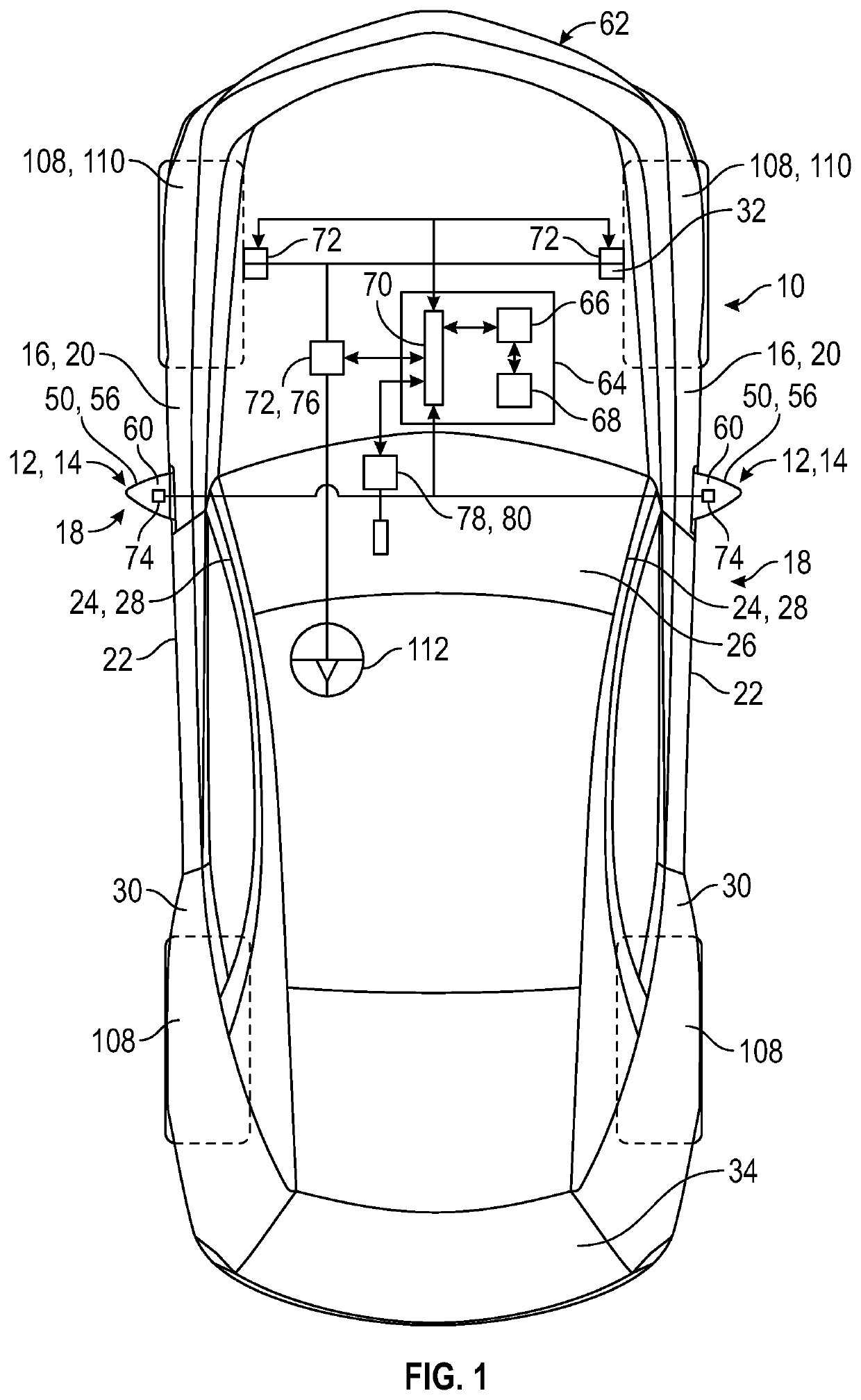
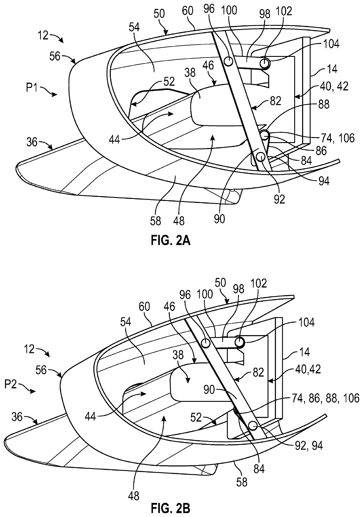
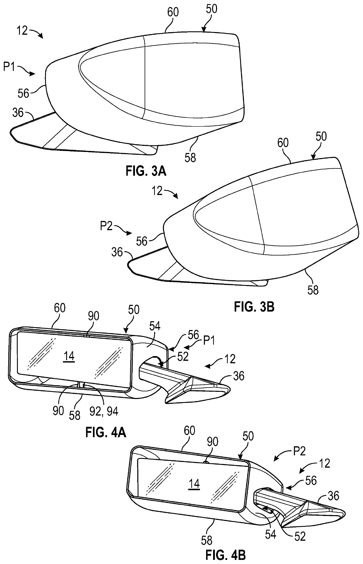
[0033]Referring now to the drawings, wherein like reference numbers correspond to like or similar components throughout the several figures, the terms “forward”, “rear”, “inner”, “inwardly”, “outer”, “outwardly”, “above”, and “below” are terms used relative to the orientation of a vehicle 10 as shown in the drawings of the present application. Thus, “forward” refers to a direction toward a front of a vehicle 10, “rearward” refers to a direction toward a rear of a vehicle 10, “inner” and “inwardly” refers to a direction towards the interior of a vehicle 10, and “outer” and “outwardly” refers to a direction towards the exterior of a vehicle 10, “below” refers to a direction towards the bottom of the vehicle 10, and “above” refers to a direction towards a top of the vehicle 10.

[0034]Additionally, in the claims and specification, certain elements are de...


PUM


Abstract

An active outside rear view system for a vehicle includes a support structure mounted to an exterior surface of the vehicle. A rear view device is movably affixed to the support structure. A linkage extends from a first end to a second end, where the first end of the linkage is movably affixed to an aerodynamic enclosure and the second end of the linkage is movably affixed to the support structure. An actuator is engaged with the linkage and moves the aerodynamic enclosure between at least a first position and a second position different from the first position. The aerodynamic enclosure is independently movable relative to the rear view device and the support structure. The aerodynamic first position and the second position provide differing aerodynamic characteristics to the active outside rear view system.

Description

INTRODUCTION[0001]The present disclosure generally relates to vehicles, and more specifically to rear-view devices mounted to motor vehicle exteriors. Outside rear view mirrors (OSRVMs) are mounted to exterior surfaces of motor vehicles and provide a motor vehicle driver with rearward-facing views of areas to the sides and behind the motor vehicle to which the OSRVMs are attached. Current OSRVMs are often enclosed in a stylized housing or enclosure that is rigidly mounted relative to the vehicle and designed to operate in a single state. The housings or enclosure protrude into airflow around the motor vehicle and can have an impact on wind noise, aerodynamic drag, and the like. Accordingly, OSRVM housings are typically shaped to achieve a specific aesthetic design and aerodynamic characteristics, such as increased downforce. However, each aerodynamic criterion selected for a typical single state OSRVM housing may increase certain undesirable characteristics, such as increased wind n...

Claims


Application Information

Patent Timeline
Patent Type & Authority Applications(United States)
IPC IPC(8): B60R1/07B62D37/02B60R1/062B60R1/12
CPCB60R1/07B62D37/02B60R2001/1253B60R1/12B60R2001/1223B60R1/0625B60R1/06B62D35/005Y02T10/82
Inventor CAPLES, DAVID C.
Owner GM GLOBAL TECH OPERATIONS LLC
Why Eureka
Try Eureka