Split linkage mechanism for valve assembly

a linkage mechanism and valve assembly technology, applied in the field of valves, can solve the problems of nox and particulate formation, the linkage mechanism is incapable of accommodating any significant tolerance stackup, and the anti-backdrive feature will be diminished, so as to achieve good anti-backdrive capability, good low flow resolution, and high opening force

Active Publication Date: 2019-11-12
BORGWARNER INC
View PDF15 Cites 1 Cited by
  • Summary
  • Abstract
  • Description
  • Claims
  • Application Information

AI Technical Summary

Benefits of technology

[0009]One advantage of the present invention is that a new linkage mechanism is provided for a valve assembly used in a vehicle. Another advantage of the present invention is that the linkage mechanism is used to pull a valve member of the valve assembly open. Yet another advantage of the present invention is that the linkage mechanism includes a lever combined with a scotch yoke to create a linear range of motion of an initial opening region of travel of the valve member. Still another advantage of the present invention is that the linkage mechanism may be capable of providing desired characteristics of good low flow resolution, high opening force, and good anti-backdrive capability over a range of valve lift while being tolerant to components and manufacturing processes. A further advantage of the present invention is that the linkage mechanism may avoid undesirable characteristics that may include a high pressure angle that may increase side loading of valve components of the valve assembly.
[0010]Other objects, features, and advantages of the present invention will be readily appreciated as the same becomes better understood after reading the subsequent description taken in connection with the accompanying drawings.

Problems solved by technology

The exhaust gas portion of the mixture may not support combustion and, when this mixture is compressed and ignited in a cylinder of the engine, the exhaust gas may control the combustion temperature and limit the formation of NOx and particulate in the exhaust emissions.
This means the linkage mechanism is incapable of accommodating any significant tolerance stackup, especially if the valve seat is in a mating part, and the valve will fail to reach the seat.
Conversely, if the starting angle is too high, the anti-backdrive feature will be diminished, and the valve may be subject to blowing open at high delta pressures.
This translates to a larger motor, return spring, package size, and cost.

Method used


Image

  • Split linkage mechanism for valve assembly
  • Split linkage mechanism for valve assembly
  • Split linkage mechanism for valve assembly

Examples


Embodiment Construction

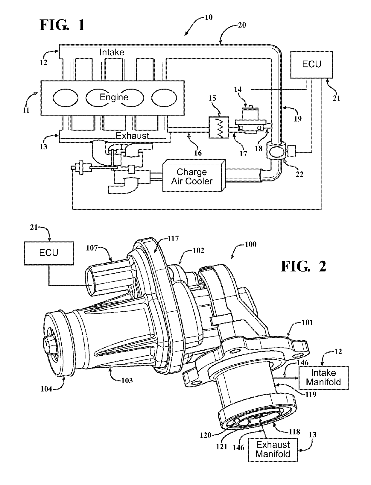
[0037]Referring now to the figures, where like numerals are used to designate like structure unless otherwise indicated, one embodiment of an EGR system 10 is shown in FIG. 1 for a vehicle (not shown). The vehicle includes an engine 11. In one embodiment, the engine 11 is a conventional internal combustion engine known in the art. The engine 11 has an intake manifold 12 and an exhaust manifold 13. The EGR system 10 is used to control combustion temperatures, and control Nox and particulate emissions from the engine 11. It should be appreciated that the engine could be of any suitable type to drive the vehicle, without departing from the scope of the present invention.

[0038]As illustrated in FIG. 1, the EGR system 10 may include an exhaust gas recirculation (EGR) valve 14 that may control the flow of exhaust gas to the intake manifold 12 and an EGR cooler 15 to reduce a temperature of the exhaust gas entering the intake manifold 12. The EGR system 10 also may include one or more cond...


PUM


Abstract

A linkage mechanism for a valve assembly includes one of a slot and an engagement component operably coupled to at least one drive component and located eccentrically from a rotational axis of the at least one drive component, a link operably coupled to one end of a valve stem of a valve member and being moveable with the valve stem, the link having another one of a slot and an engagement component, and a rotatable lever coupled to at least one housing, the lever including one of a first slot and a first engagement component operably engaged with the one of the slot and the engagement component of the at least one drive component and one of a second slot and a second engagement component operably engaged with the one of the slot and the engagement component of the link, wherein rotation of the at least one drive component causes the lever to rotate to convert a rotational movement of the at least one drive component to a linear movement of the link such that the link, the valve stem, and the valve member are moved axially in a direction along a longitudinal axis of the valve stem.

Description

BACKGROUND OF INVENTION1. Field of Invention[0001]The present invention relates generally to valves such as an air throttle valve, exhaust gas recirculation (EGR) valve, exhaust throttle valve, bypass valve, turbo waste gate valve, or recirculation valve used for vehicles and, more specifically, to a linkage mechanism for a valve assembly used in a vehicle that may afford improved performance over a range of operation of the valve assembly.2. Description of the Related Art[0002]Control of vehicle engine exhaust emissions and meeting fuel economy standards are mandatory requirements in most countries. Oxides of Nitrogen (NOx) and particulate matter are two components of the engine exhaust emissions that must be controlled.[0003]Formation of NOx may occur at higher engine combustion temperatures and particulates may form at lower combustion temperatures. A system, referred to as an exhaust gas recirculation (EGR) system, has been developed to control combustion temperatures, NOx, and ...

Claims


Application Information

Patent Timeline
Patent Type & Authority Patents(United States)
IPC IPC(8): F02M26/52F16K31/53F16K31/524F02M26/68F16K31/60
CPCF16K31/5245F16K31/53F02M26/52F16K31/602F02M26/68F02M26/54F02M26/66
Inventor TELEP, ROBERT J.KEEFOVER, ROBERT D.
Owner BORGWARNER INC
Why Eureka
Try Eureka