
Active light-emitting type target for automatic calibration based on machine vision and calibrating method thereof

An automatic calibration and machine vision technology, applied in the field of computer vision, can solve problems such as complex program algorithms, missed calibration points, misjudged calibration points, etc., and achieve the effect of accurate internal and external parameters and low cost

Inactive Publication Date: 2012-06-27
NANJING UNIV
View PDF4 Cites 16 Cited by
  • Summary
  • Abstract
  • Description
  • Claims
  • Application Information

AI Technical Summary

Problems solved by technology

However, the general disadvantage of these schemes is that the interference of the background environment cannot be eliminated. If there are characteristic patterns similar to the target or other disturbing factors in the background, it is easy to misjudge the calibration point or miss the calibration point.
Moreover, this kind of program algorithm usually tends to be complicated, and some programs have high requirements for target production

Method used

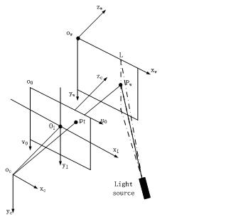

Image

  • Active light-emitting type target for automatic calibration based on machine vision and calibrating method thereof
  • Active light-emitting type target for automatic calibration based on machine vision and calibrating method thereof
  • Active light-emitting type target for automatic calibration based on machine vision and calibrating method thereof

Examples


Embodiment Construction

[0022] specific implementation plan

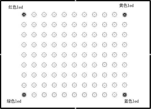
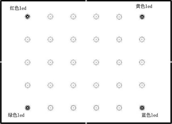
[0023] The target designed by the present invention is embedded with several light-emitting small lights arranged in a rectangular lattice, for example, the distribution of rows and columns is 9x11. All the small lights are arranged at equal intervals in the horizontal and vertical directions. The small lights on the four vertices of the rectangle are distinctive and have different colors. Each small lamp is controlled by an independent switch, and the switch of the small lamps in the array can be controlled by the program later.

[0024] The specific calibration process is as follows:

[0025] Step 1: Place the target at different positions in the field of view of the camera, and take multiple sets of color images. Each location takes a picture of the small light on and off. When shooting, use the main switch to control the small lights, and the position of the target in each group of pictures remains unchanged.

[0026] Step 2: First...


PUM


Abstract

The invention relates to an active light-emitting type target calibrating method for automatic calibration based on machine vision. A plurality of small light emitting lamps arranged into a rectangular dot matrix are embedded on a target of a two-dimensional flat plate type, and all the small lamps are arranged equidistantly in a horizontal direction and a vertical direction, and colors of the four small light-emitting lamps on the four vertexes of the rectangular dot matrix are different; each small light-emitting lamp is controlled by an independent switch; and the operating modes of the target include a remote operating mode and a close operating mode: when the target is arranged at a close place, all the small light-emitting lamps on the target are opened; when the target is arranged at a remote place, the small light-emitting lamps with different colors at the four corners of the target are opened, and the residual small light-emitting lamps emit light every two columns. The calibrating method comprises the following steps of: shooting multiple groups of target images from any selected different positions by a camera, and respectively shooting one opening image and one closing image of the small light-emitting lamps at the same position; removing the background of each group of images by using a grey difference subtraction method; extracting a light emitting central point (calibrating point) of each small light-emitting lamp by using a grey gravity method; and directly substituting the obtained data into the camera calibration algorithm to calculate inner and outer parameters of the camera.

Description

Technical field: [0001] The invention relates to an active luminous type target which can be used for automatic calibration of machine vision and a calibration method thereof, belonging to the field of computer vision. Background technique: [0002] At present, camera calibration methods in machine vision are mainly divided into traditional calibration methods and self-calibration methods. The former requires the use of calibration objects, and the two-step method is relatively mature; while self-calibration does not require reference calibration objects, and only solves the camera parameters through the relationship between image sequences, but this method is still insufficient in terms of stability and accuracy. [0003] However, to use the traditional calibration method to realize the automatic calibration of camera parameters, the core key is to be able to automatically identify the calibration points. Most of the current solutions use a target with a specific geometric...

Claims


Application Information

Patent Timeline
IPC IPC(8): G06T7/00
Inventor 郭亚敏肖舰戚力俞乾张益昕王顺张旭苹
Owner NANJING UNIV
Learn More