
Differential driving circuit and driving system for powering a light source

A drive system and differential drive technology, applied in the field of drive systems, can solve the problems of high rated voltage and high switching cost, and achieve the effect of reducing rated voltage, obvious characteristics and advantages, and reducing costs

Inactive Publication Date: 2012-06-27
AOTU ELECTRONICS WUHAN
View PDF4 Cites 7 Cited by
  • Summary
  • Abstract
  • Description
  • Claims
  • Application Information

AI Technical Summary

Problems solved by technology

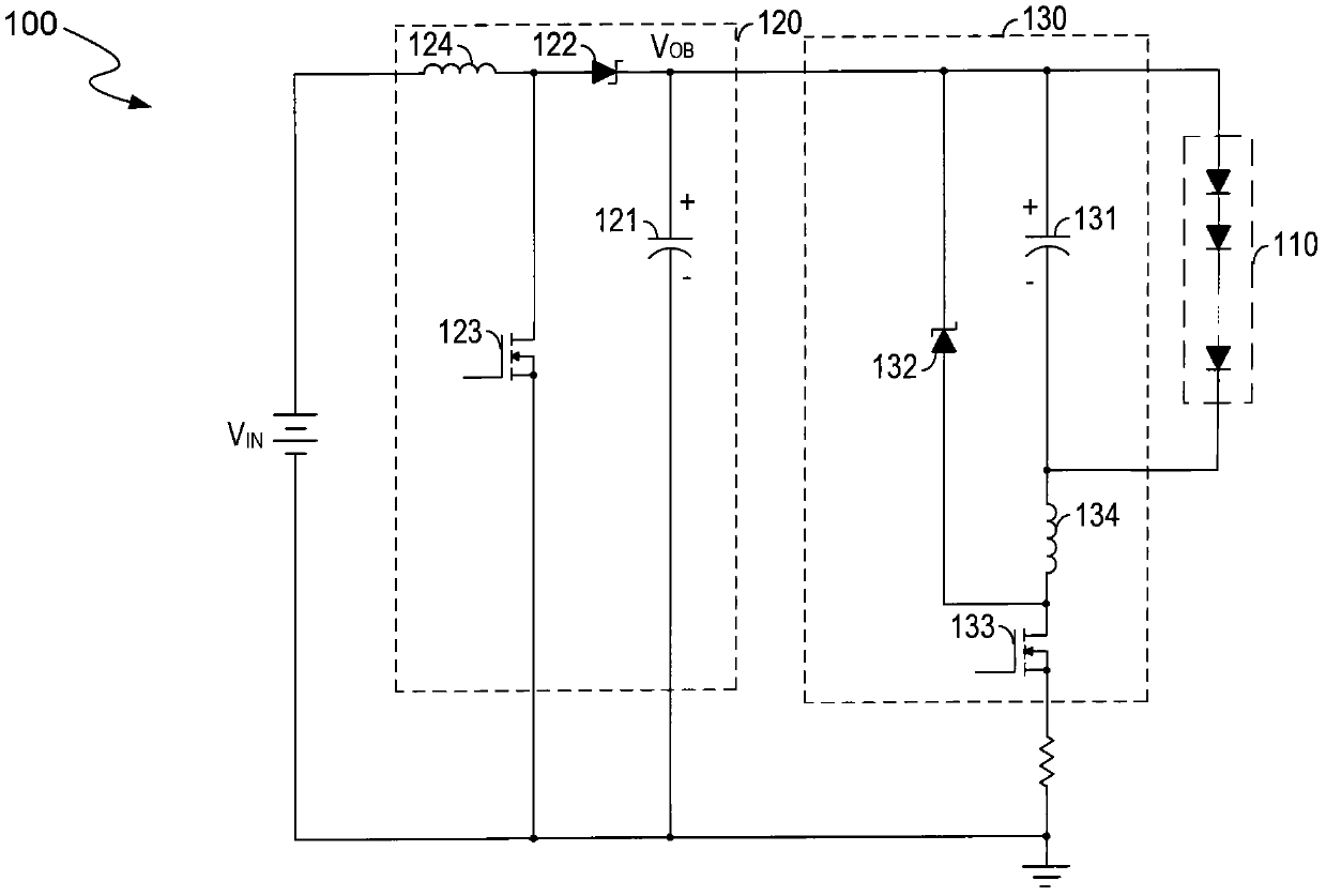
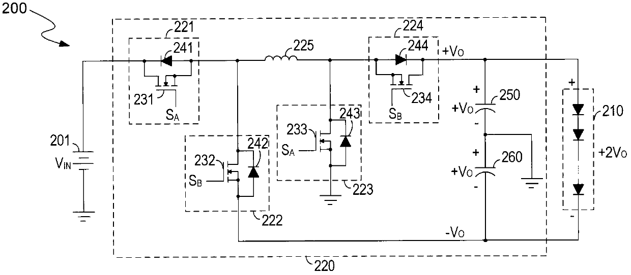
[0004] In order to solve the technical problem that the rated voltage of the circuit elements in the drive circuit in the prior art is relatively high, resulting in relatively high switching costs, the present invention provides a differential drive circuit powered by a light source

Method used


Image

  • Differential driving circuit and driving system for powering a light source
  • Differential driving circuit and driving system for powering a light source
  • Differential driving circuit and driving system for powering a light source

Examples


Embodiment Construction

[0015] A detailed description will be given below of embodiments of the present invention. While the invention will be described in conjunction with examples, it will be understood that it is not intended to limit the invention to these examples. On the contrary, the invention is intended to cover various alternatives, modifications and equivalents as defined within the spirit and scope of the invention as defined by the appended claims.

[0016] Furthermore, in the following detailed description of the invention, numerous specific details are set forth in order to provide a thorough understanding of the invention. However, it will be understood by those skilled in the art that the present invention may be practiced without these specific details. In some other embodiments, well-known schemes, processes, components and circuits are not described in detail, so as to highlight the gist of the present invention.

[0017] In one embodiment, the present invention discloses a diff...


PUM


Abstract

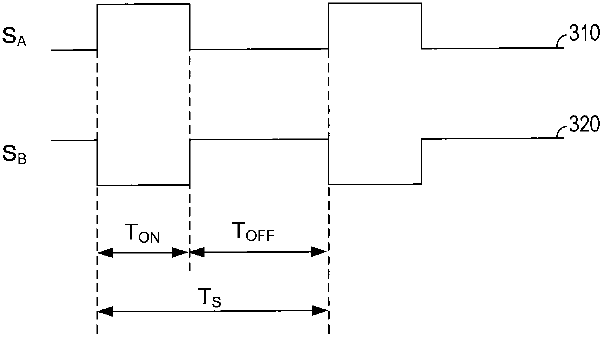
The invention discloses a differential driving circuit for powering a light source and a driving system. The differential driving circuit includes a first set of switches and a second set of switches. A first current from a power source flows through the first set of switches to charge a first energy storage element when the first set of switches are turned on. A second current from the first energy storage element flows through the second set of switches to power the light source when the second set of switches are turned on. The differential driving circuit further includes a second energy storage element coupled to the light source in parallel and for providing a differential voltage to the light source. The invention also discloses a driving system for powering a light source, comprising a first switch, a second switch, a third switch and a fourth switch. A first signal controls conducting states of the first switch and the second switch; a second signal controls conducting statesof a third switch and a fourth switch so as to adjust powering to the light source. The nominal voltage of the differential driving circuit is reduced and switch costs are reduced.

Description

technical field [0001] The present invention relates to a driving system, in particular to a differential driving circuit. Background technique [0002] LED light-emitting diodes (light-emitting diodes, LEDs for short) can be used as backlights in various application systems, such as notebooks, liquid crystal displays, and liquid crystal display televisions. For example, multiple LED strings including hundreds of LEDs may be employed in large LCD televisions. The driver circuit supplies power to the LED strings. In order to reduce the cost of the driving circuit, the LEDs are arranged in parallel LED strings. Likewise, in order to contain a small number of LED strings connected in parallel, each LED string contains a plurality of LEDs connected in series. Therefore, the voltage of the LED string is relatively high. The relatively high voltage produces greater stress on some circuit components of the drive circuit, and the cost of the drive circuit increases to accommodat...

Claims


Application Information

Patent Timeline
IPC IPC(8): G09G3/34H05B44/00
CPCH02M3/158H05B33/0815H05B45/3725
Inventor 林永霖郭清泉
Owner AOTU ELECTRONICS WUHAN
Learn More