Dc-dc converter

A DC-DC and converter technology, applied in the field of DC-DC converters, can solve problems such as high cost and reduced maximum reverse voltage

Active Publication Date: 2019-10-11
VTESCO TECH GMBH
View PDF12 Cites 0 Cited by
  • Summary
  • Abstract
  • Description
  • Claims
  • Application Information

AI Technical Summary

Problems solved by technology

However, there is also an additional problem here: in the case of many currently used semiconductors, their maximum reverse voltage is reduced at low temperatures
This leads to higher costs due to its space requirements on the circuit board and of course due to component costs

Method used


Image

  • Dc-dc converter

Examples


Embodiment Construction

[0016] A DC-DC converter typically provides energy at its own output from an input energy source by intermediate storage as magnetic energy in a coil, as electrical energy stored in an output capacitor, wherein the The voltage across the output capacitor is regulated to a predetermined value. The DC-DC converter can be designed here as a step-down converter, a step-up converter or an inverting converter, a primary-clocked or a secondary-clocked converter.

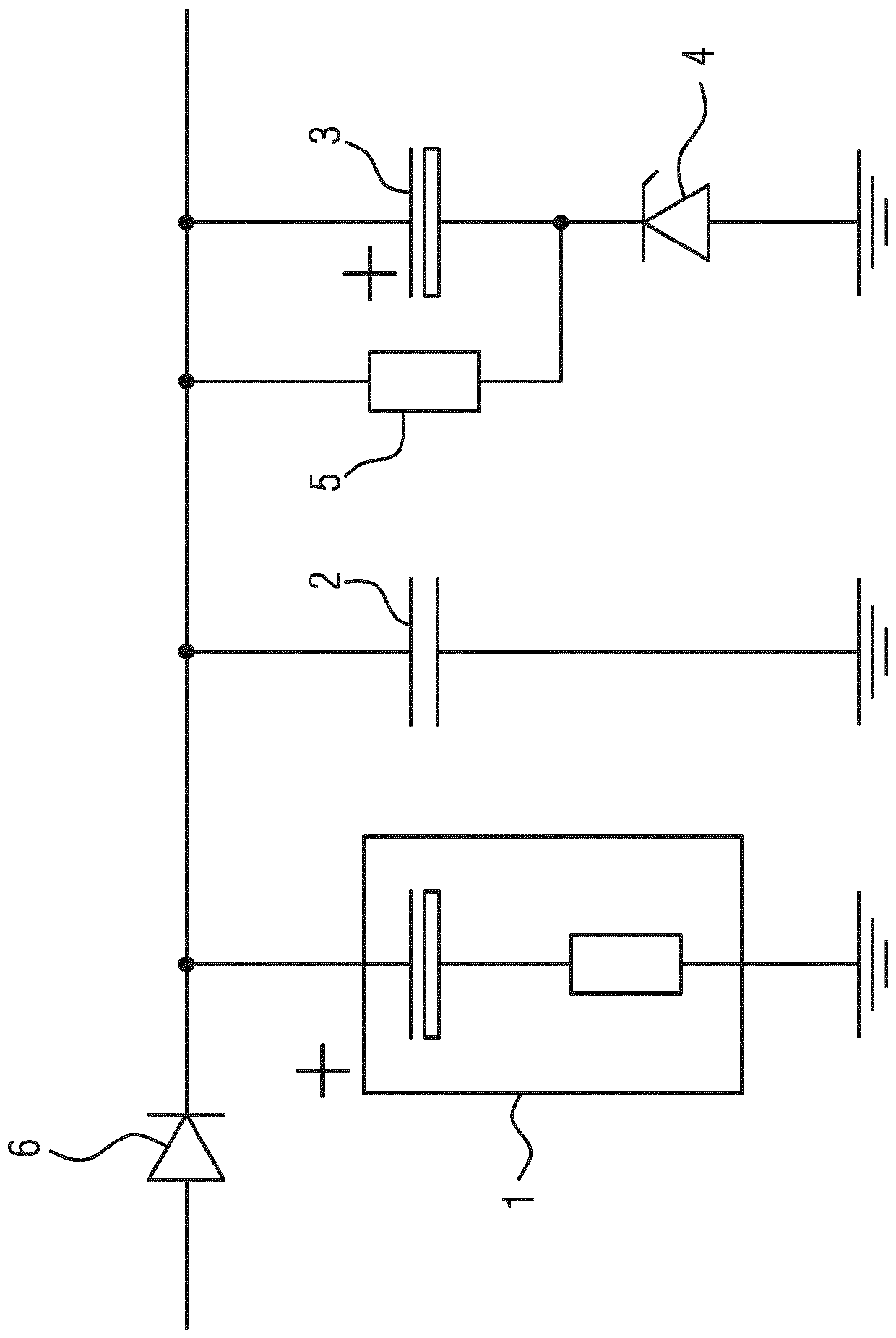
[0017] The output capacitor is used as a storage capacitor and in accordance with the present invention the figure 1 In the storage capacitor device, an electrolytic capacitor 1, a ceramic capacitor 2 connected in parallel with it, a series circuit composed of a hybrid electrolytic capacitor 3 and a suppression diode 4 connected in parallel with it, and a series circuit connected in parallel with the hybrid electrolytic capacitor 3 Resistor 5 to form. The storage capacitor arrangement is connected to the DC-DC converter ...


PUM


Abstract

The invention relates to a DC-DC converter with an output-sided storage capacitor assembly, which is formed from of a parallel connection of an electrolytic capacitor (1), a ceramic capacitor (2) anda circuit arrangement with a series connection of a hybrid electrolyte capacitor (3) and a suppressor diode (4) and a resistor (5) which is connected in parallel to the hybrid electrolyte capacitor (3).

Description

technical field [0001] The invention relates to a DC-DC converter with an output-side storage capacitor arrangement. Background technique [0002] Such a DC-DC converter is known from DE 10 2007 001 414 B3, in which a storage capacitor arrangement with electrolytic capacitors is formed. [0003] In the field of automotive electronics, such DC-DC converters are used for operating solenoid-operated fuel injectors, wherein the electrolytic capacitor is provided for supplying the operating voltage for such an inductive load, so that the solenoid During the actuation of the tubes, comparatively high currents can be supplied briefly in a simple manner. Furthermore, the principle is known to provide a feedback of electrical energy into the electrolytic capacitor after switching off the solenoid, so that the energy stored back can be used in the event of a subsequent solenoid actuation. [0004] As shown and described in detail in DE 10 2007 001 414 B3, electrolytic capacitors fre...

Claims


Application Information

Patent Timeline
Patent Type & Authority Applications(China)
IPC IPC(8): H02M1/34F16K31/06F02D41/20H02M3/155H01G11/04H01G11/08
CPCH01G11/04H01G11/08H02M3/155F02D2041/2006Y02E60/13H02M3/1555H01H11/04H02M3/33576H02M3/33546G05F1/46H02H9/00H02M7/06H05B44/00
Inventor A.迈尔-迪克
Owner VTESCO TECH GMBH
Why Eureka
Try Eureka