Tapped speed regulation method of low-voltage brushless direct current motor
A technology of DC motor and speed regulation method, which is applied in the direction of single motor speed/torque control, etc., can solve the problems of increasing the cost of brushless DC motors, and achieve the effect of reducing costs
- Summary
- Abstract
- Description
- Claims
- Application Information
AI Technical Summary
Problems solved by technology
Method used
Image

Examples
Embodiment 1
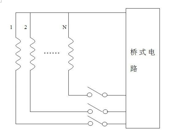
[0022] Embodiment 1 of the present invention describes a single-phase low-voltage brushless DC motor tapped speed regulation method, in which a multi-strand winding coil is wound on the stator core of the brushless DC motor, and the multi-strand winding coil The multi-strand winding wires are wound side by side in the slot of the stator core, and one end of the multi-strand winding coil is connected to the controller of the motor through an electronic switch or a mechanical switch. The wiring method of the winding of the brushless DC motor is as follows: the N-strand winding wires of the multi-strand winding are wound in parallel, the ends of all the winding wires with the same name are connected together and connected to a bridge of the bridge circuit, and the other end of the winding wire is single After the strands or multiple strands are connected in parallel, they are respectively connected to another bridge in the bridge circuit through a plurality of electronic switches ...
Embodiment 2
[0024] This matter example 2 is changed on the basis of embodiment 1, and it is mainly the difference of wiring mode, specifically as follows:
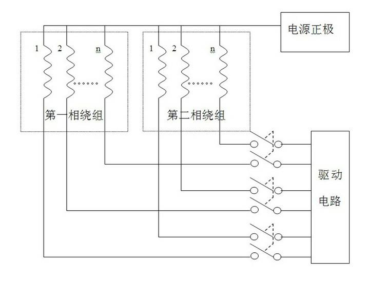
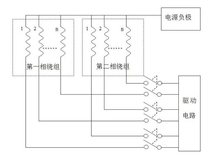
[0025] The brushless DC motor of this embodiment 2 is a two-phase brushless DC motor, and its wiring method is:
[0026] Two multi-strand winding coils are wound on the stator core, and the N-strand winding wires of each multi-strand winding coil are wound in parallel, and the end of the winding wire of each multi-strand winding coil is connected to the positive or negative pole of the power supply. The other end of the winding wire of each multi-strand winding is respectively connected to the driving circuit through a plurality of electronic switches or mechanical switches. Its wiring method is as figure 2 and image 3 shown.
Embodiment 3
[0028] This matter example 3 is changed on the basis of embodiment 1 equally, and it is mainly the difference of wiring mode, specifically as follows:
[0029] The brushless DC motor of the present embodiment 3 is a three-phase brushless DC motor, and its wiring method is:
[0030] Three multi-strand winding coils are wound on the stator core, and the multi-strand winding wires of each multi-strand winding coil are wound together, and one end of the winding wire of each multi-strand winding coil is respectively connected to the three ends of the bridge circuit. On a bridge, the winding wire of each multi-strand winding coil is connected to the other single-strand or multi-strand with the same name and then short-circuited by multiple electronic switches or mechanical switches. The wiring of the motor is as follows Figure 4 shown.
PUM
 Abstract
Description
Claims
Application Information
 - R&D
- Intellectual Property
- Life Sciences
- Materials
- Tech Scout
- Unparalleled Data Quality
- Higher Quality Content
- 60% Fewer Hallucinations
Browse by: Latest US Patents, China's latest patents, Technical Efficacy Thesaurus, Application Domain, Technology Topic, Popular Technical Reports.
© 2025 PatSnap. All rights reserved.Legal|Privacy policy|Modern Slavery Act Transparency Statement|Sitemap|About US| Contact US: help@patsnap.com