
Reservoir ink-filling machine

A technology for wrapping and filling ink, which is applied in the directions of ink filling device, ink container, printing, etc., can solve the problems of reducing writing length, large manual workload, uneven ink filling, etc., to avoid ink leakage and drip point, Improve the efficiency of ink filling and ensure the effect of writing length

Active Publication Date: 2012-07-04
NINGBO BEIFA GRP CO LTD
View PDF4 Cites 4 Cited by
  • Summary
  • Abstract
  • Description
  • Claims
  • Application Information

AI Technical Summary

Problems solved by technology

The traditional method of filling ink is to bundle core-spun rolls into bundles of core-spun bundles first, and then the operator takes the bundle of core-spun rolls in one hand and the syringe with ink in the other hand, and then injects ink into the core-spun rolls one by one. However, the amount of ink injected into the cores of each roll is completely determined by the subjective judgment of the operator, which will lead to uneven ink filling in the cores of each roll, and the cores with less ink filling will reduce the writing length. The roll-spun core with a large amount of ink filling may cause ink leakage and dripping during use; on the other hand, the efficiency of this traditional ink filling method is very low; Bind the roll cores into roll core bundles, and then inject ink into the roll cores manually, which requires a huge amount of manual work

Method used


Image

  • Reservoir ink-filling machine
  • Reservoir ink-filling machine

Examples


Embodiment Construction

[0013] The present invention will be further described in detail below in conjunction with the accompanying drawings and embodiments.

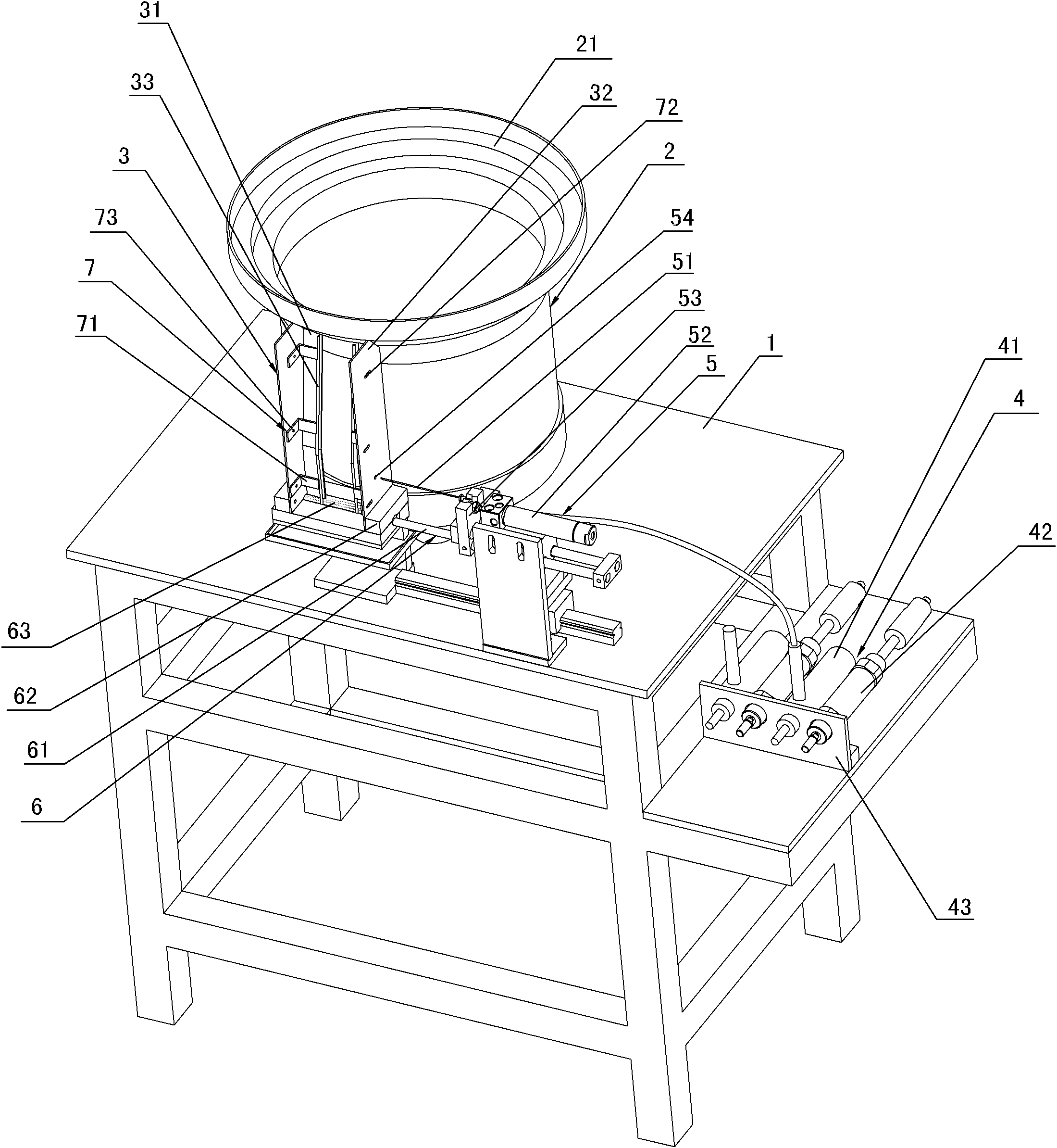
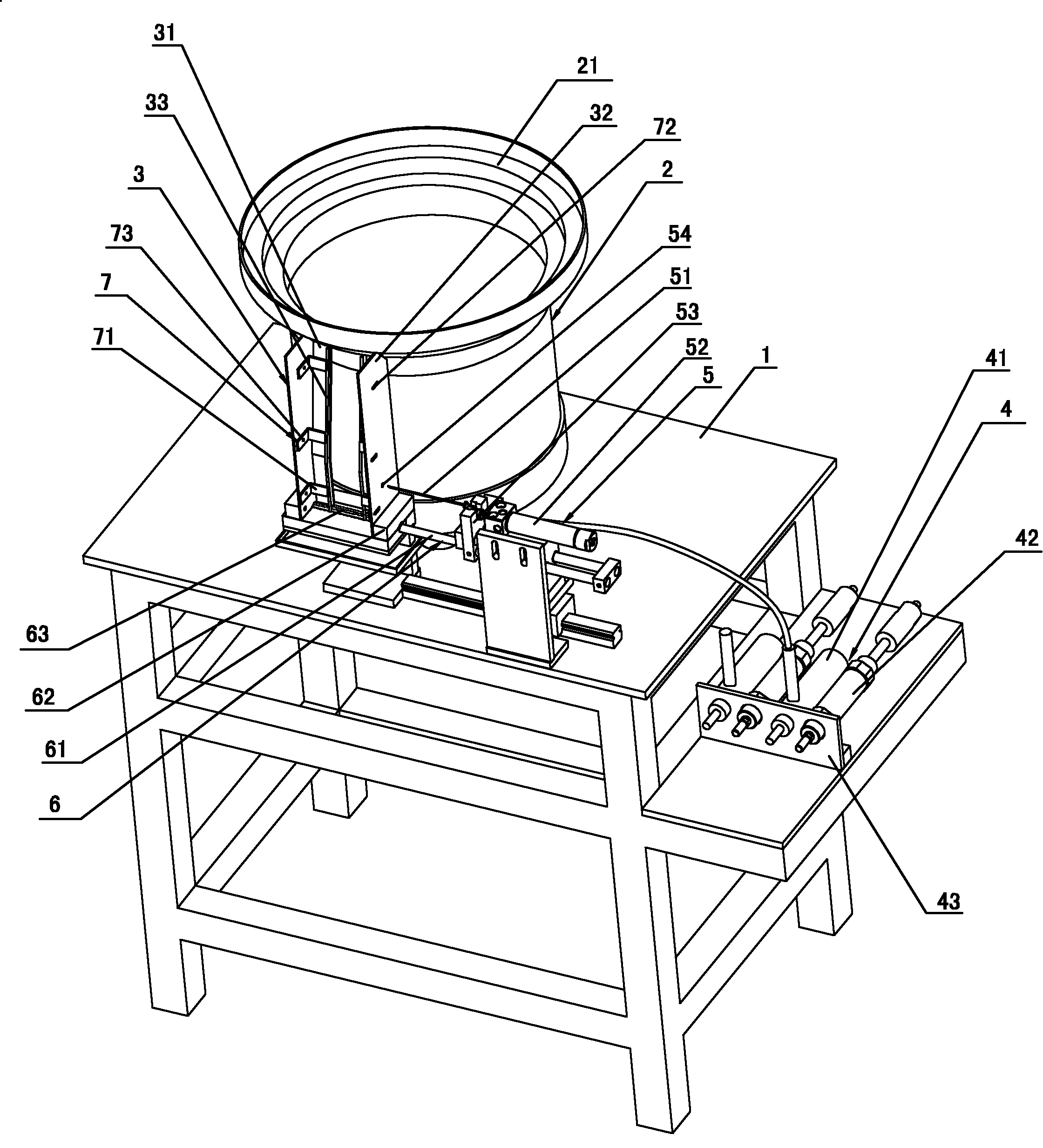
[0014] A kind of volume core ink filling machine that the present invention proposes, as figure 1 As shown, it includes a frame 1 and a feeding mechanism 2 arranged on the frame 1, a feeding arrangement rail 3, an ink filling mechanism 4, an ink filling mechanism 5, a pushing mechanism 6 and a controller (not shown in the figure) , the feeding mechanism 2 is mainly composed of a directional feeding vibrating plate 21 and a vibrating motor (not shown in the figure) connected to the directional feeding vibrating plate 21, and the ink filling mechanism 4 is mainly composed of a plug pump 41, an ink filling cylinder 42 and the first connection plate 43, the ink filling mechanism 5 is mainly composed of an ink injection needle 51, a needle tube cylinder 52, a second connecting plate 53, and a positioning through hole 54 arranged on the feeding arra...


PUM


Abstract

The invention discloses a reservoir ink-filling machine which comprises a machine frame, a feeding mechanism, a feeding arrangement rail, an ink injecting mechanism, an ink filling mechanism and a controller, wherein the feeding mechanism, the feeding arrangement rail, the ink injecting mechanism, the ink filling mechanism and the controller are mainly arranged on the machine frame, the feeding mechanism mainly comprises a directional feeding vibrating disc, the ink injecting mechanism is composed of a plunger pump, an ink injecting cylinder and a first connecting plate, the ink filling mechanism is composed of an ink feeding needle, a needle tube cylinder and a second connecting plate, and the pushing mechanism is composed of a push rod and a locating block; the ink injecting cylinder drives the transmission shaft of the plunger pump to reciprocate so as to enable the plunger pump to suck ink from an ink box and discharge the ink into the ink feeding needle; the needle tube cylinder drives the ink feeding needle and the push rod to reciprocate; when the ink feeding needle moves to reservoirs on the feeding arrangement rail, ink in the ink feeding needle is just filled into the reservoirs, and the push rod pushes off the reservoirs which fall in a locating groove on the locating block from the feeding arrangement rail and are filled with ink; and the amount of ink that the plunger pump sucks each time is constant, so that ink filled in each reservoir is uniform. The reservoir ink-filling machine has the advantage of not only ensuring the writing amount but also avoiding the phenomenon of ink leakage.

Description

technical field [0001] The invention relates to an ink filling device, in particular to a roll core ink filling machine. Background technique [0002] At present, most of the highlighters, markers, and whiteboard pens that are popular in the market use roll cores to store ink. The nib cover is inserted into the roll core, and the roll core needs to be filled with ink before use. The traditional method of filling ink is to bundle core-spun rolls into bundles of core-spun bundles first, and then the operator takes the bundle of core-spun rolls in one hand and the syringe with ink in the other hand, and then injects ink into the core-spun rolls one by one. However, the amount of ink injected into the cores of each roll is completely determined by the subjective judgment of the operator, which will lead to uneven ink filling in the cores of each roll, and the cores with less ink filling will reduce the writing length. The roll-spun core with a large amount of ink filling may c...

Claims


Application Information

Patent Timeline
Patent Type & Authority Applications(China)
IPC IPC(8): B43K11/00
CPCB43L25/007B43K11/005
Inventor 董财良朱锋
Owner NINGBO BEIFA GRP CO LTD
Learn More