Adjustment of wings for variable camber for optimum take-off and landing configuration

A technology of wings and aircraft, applied in the field of high lift equipment, can solve problems such as differential moving flaps

Active Publication Date: 2012-07-04
THE BOEING CO
View PDF6 Cites 8 Cited by
  • Summary
  • Abstract
  • Description
  • Claims
  • Application Information

AI Technical Summary

Problems solved by technology

However, no such system exists that is designed to differentially move the flaps in a manner suitable for takeoff and landing

Method used


Image

  • Adjustment of wings for variable camber for optimum take-off and landing configuration
  • Adjustment of wings for variable camber for optimum take-off and landing configuration
  • Adjustment of wings for variable camber for optimum take-off and landing configuration

Examples


Embodiment Construction

[0116] In the following detailed description, certain preferred embodiments are described by way of illustration in specific application contexts in order to provide a thorough understanding of the present disclosure. Methods, procedures, components and functions that are generally known to those skilled in the art of the disclosure have not been described in detail so as not to unnecessarily obscure the concise description of the present disclosure. Certain specific embodiments or examples are given for illustration only, and those skilled in the art will recognize that the teachings of the present disclosure may be practiced in other similar applications or environments, and / or with other similar or equivalent variations of the illustrated embodiments. .

[0117] Some portions of the detailed description below are presented in terms of procedures, steps, logical blocks, processing and other symbolic representations of operations within computer memory. These descriptions an...


PUM


Abstract

This application is directed to systems and methods for moving trailing edge high lift devices on an aircraft wing, and more particularly to moving inboard, outboard and midspan flaps differentially in order to produce better lift / drag characteristics during takeoff and landing of the aircraft.

Description

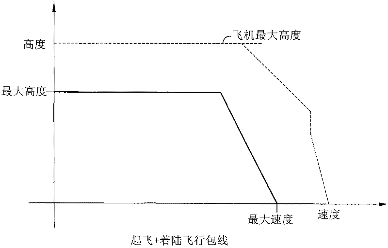
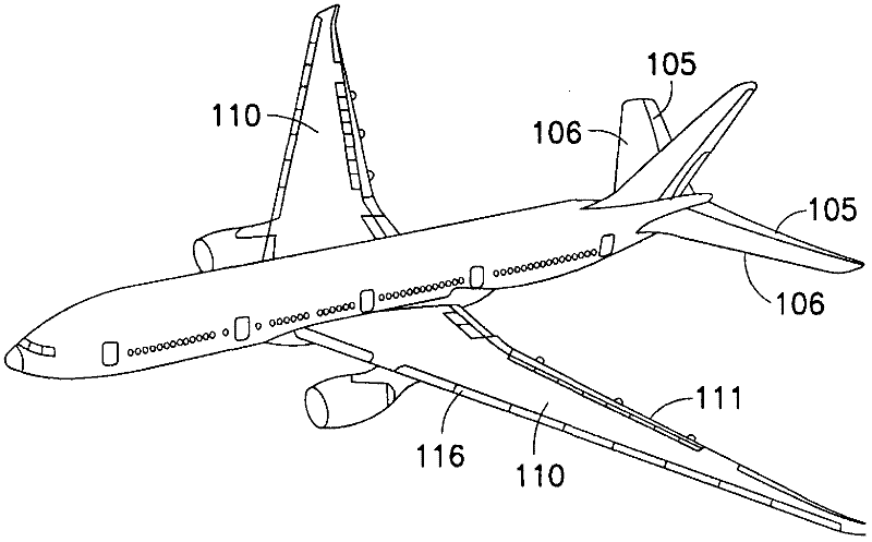
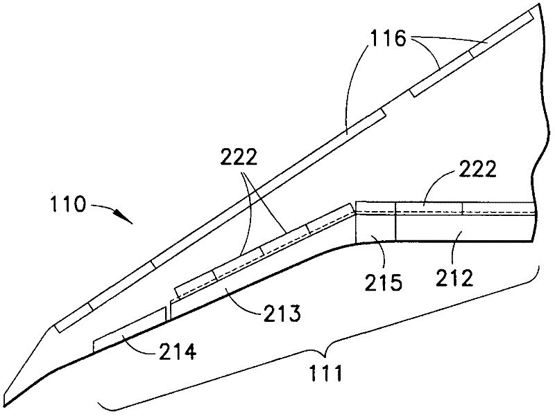
technical field [0001] The present application relates to systems and methods for moving trailing edge high-lift devices on aircraft wings, and more particularly to differentially moving inboard, outboard, and midsection flaps to create better lift / drag characteristics during takeoff and landing of an aircraft. Background technique [0002] During take-off and landing, trailing-edge high-lift devices placed on the trailing edge of an aircraft wing are used to provide lift at the expense of increased drag and reduce the stall speed of the aircraft. Trailing edge high-lift devices include surfaces, such as flaps, that are movable from a stowed position to a deployed position. The flaps may include an inboard flap positioned closer to the fuselage, an outboard flap positioned further from the fuselage, and a midsection flap positioned between the inboard and outboard flaps. [0003] Flap control may be provided automatically by a controller within the aircraft, or manually by ...

Claims


Application Information

Patent Timeline
Patent Type & Authority Applications(China)
IPC IPC(8): B64C9/06B64C13/02B64C13/24
CPCY02T50/44B64C9/20B64C9/24Y02T50/32B64C13/16Y02T50/30Y02T50/40
Inventor M·古德P·约翰逊
Owner THE BOEING CO
Why Eureka
Try Eureka