
Liftable mobile carrying device

A technology for transferring and lifting rods, applied in the direction of conveyor objects, furnaces, lighting and heating equipment, etc.

Inactive Publication Date: 2012-07-04
SUZHOU ZIGUAN AUTOMATIC EQUIP
View PDF8 Cites 3 Cited by
  • Summary
  • Abstract
  • Description
  • Claims
  • Application Information

AI Technical Summary

Problems solved by technology

[0004] In order to provide the above-mentioned automatic card loading equipment, a problem that needs to be solved is: in the process of transferring the vacuum tube and automatically loading the card into it, the vacuum tube needs to be transported to a designated position so that the clip can be accurately loaded into the vacuum tube

Method used


Image

  • Liftable mobile carrying device
  • Liftable mobile carrying device
  • Liftable mobile carrying device

Examples


Embodiment Construction

[0021] In order to make the object, technical solution and advantages of the present invention clearer, the present invention will be further described in detail below in conjunction with the accompanying drawings and embodiments. It should be understood that the specific embodiments described here are only used to explain the present invention, not to limit the present invention.

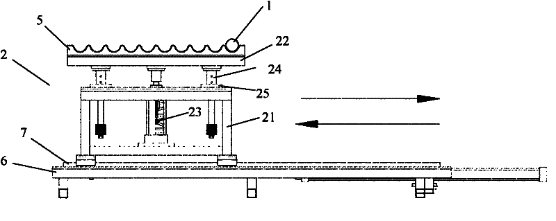
[0022] Such as image 3 and Figure 4 As shown, the present invention provides a liftable transfer device 2, comprising first and second inner transport rails 6, 7, a bracket 21 positioned on the first and second inner transport rails, and a carrier fixed above the bracket. tube platform 22, wherein,

[0023] The tube-carrying platform 22 is provided with a tube-carrying block 5, and the middle part of the support is provided with a lifting rod 23, and the lifting rod 23 supports the tube-carrying platform 22.

[0024] When working, the vacuum tube 1 is transported by the first and second outer ...


PUM


Abstract

The invention discloses a liftable mobile carrying device, which belongs to the field of card-loading technology of solar evacuated tubes, and comprises a first and a second inner transmission guide rails, a support and a tube carrying platform, wherein the support is arranged on the first and the second inner transmission guide rails, the tube carrying platform is fixed above the support, the tube carrying platform is provided with a tube carrying block, the middle portion of the support is provided with a lifting rod, and the tube carrying platform is supported by the lifting rod. The liftable mobile carrying device can transport vacuum tubes to a specific position, thereby leading cards to be capable of being loaded accurately in the vacuum tubes, and providing possibility for providing an automatic card-loading device.

Description

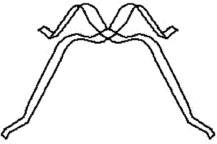
technical field [0001] The invention relates to the technical field of solar vacuum tube card loading, in particular to a liftable transfer device used in automatic card loading equipment. Background technique [0002] Solar water heaters convert sunlight energy into heat energy, and heat water from low temperature to high temperature, so as to meet the hot water use in people's life and production. The core element in the solar water heater is the heat collector, and the heat collector mainly adopts a vacuum tube, and the end of the vacuum tube needs to be loaded into a clip (used as a support). [0003] At present, in order to install clips into solar vacuum tubes, it is generally done manually. figure 1 The shown "card" is inserted into the solar vacuum tube, and the state after the card is inserted is as follows figure 2 shown. This manual loading method is slow, inefficient, and prone to accidental injury. Therefore, there is an urgent need for an automatic card lo...

Claims


Application Information

Patent Timeline
Patent Type & Authority Applications(China)
IPC IPC(8): B65G49/05
Inventor 周慧
Owner SUZHOU ZIGUAN AUTOMATIC EQUIP
Learn More