Three-station knitting cam system

A triangular system and three-station technology, applied in the field of triangular systems, can solve problems such as difficult manufacturing, installation, use and maintenance, and complex structures, and achieve the effects of low processing and manufacturing costs, simple and compact structure, and easy manufacturing, installation, and use and maintenance.

Inactive Publication Date: 2012-07-04
东阳市金艺科技有限公司
View PDF6 Cites 7 Cited by
  • Summary
  • Abstract
  • Description
  • Claims
  • Application Information

AI Technical Summary

Problems solved by technology

[0006] The present invention mainly solves the technical problems of complex structure and difficult manufacture, installation and use and maintenance in the prior art, and provides a simple structure, easy manufacture, installation and use and maintenance, low processing and manufacturing cost, and can simultaneously have braiding, tucking and Three-station knitting cam system without knitting three states

Method used


Image

  • Three-station knitting cam system
  • Three-station knitting cam system
  • Three-station knitting cam system

Examples


Embodiment Construction

[0028] The technical solutions of the present invention will be further specifically described below through the embodiments and in conjunction with the accompanying drawings.

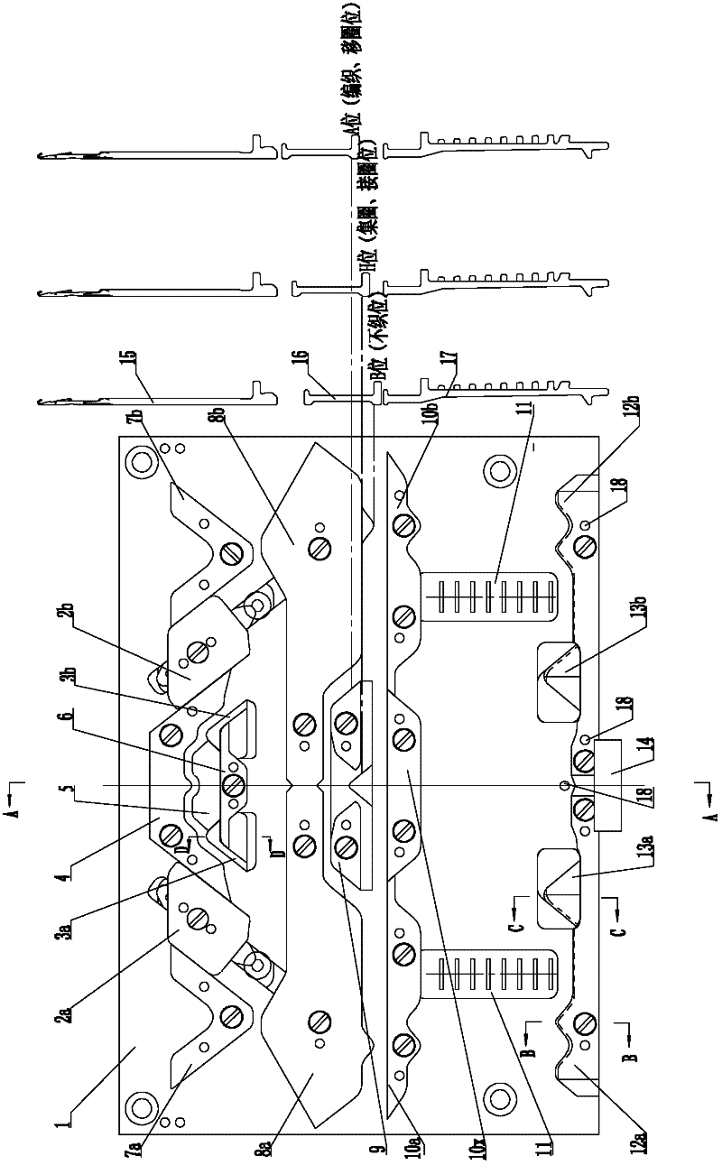
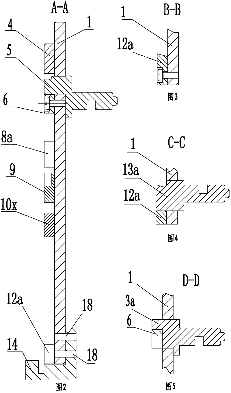
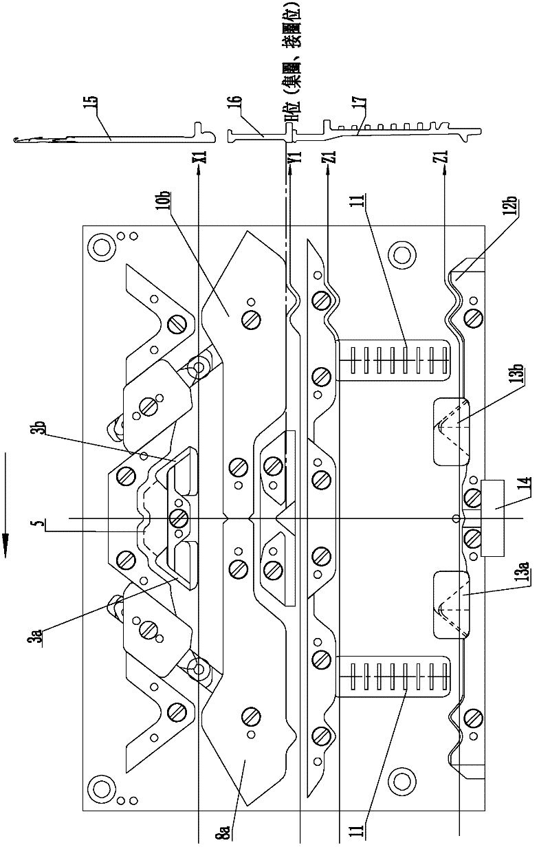
[0029] Such as figure 1 and figure 2 As shown, the present invention includes: a rectangular triangular base plate 1; a herringbone triangle 4, which is symmetrically fixed on the upper side of the front plate of the triangular base plate 1; the density triangle pair formed by the left density triangle 2a and the right density triangle 2b, The left and right density triangles 2a, 2b are symmetrically located on the left and right sides of the herringbone triangle 4 and are all connected with the front surface of the triangular bottom plate 1 by sliding fit. The sliding fit connection structure is not described here because it is a known technology; the needle guard triangle pair composed of the left needle guard triangle 3a and the right needle guard triangle 3b, the left and right needle guard trian...


PUM


Abstract

The invention relates to a cam system of a computerized flat knitting machine and discloses a three-station knitting cam system. Three states of knitting, tucking and non-knitting can be simultaneously implemented on a knitting function. The three-station knitting cam system has simple structure, is easy to install, use and maintain and has low processing and manufacturing cost. The three-station knitting cam system comprises a rectangular cam bottom plate. An inverted V-shaped cam, a knitting cam pair, a needle protecting cam pair, a density cam pair, a needle transferring cam, a middle cam, a needle guiding cam, a composite upthrowing cam, a needle selecting and protecting cam, a needle selector pair, a needle selecting and upthrowing cam pair and a needle selecting and lower needle protecting cam are bilaterally symmetrically arranged on the cam bottom plate, wherein left and right knitting cams of the knitting cam pair, the needle transferring cam and left and right needle selecting and upthrowing cams of the needle selecting and upthrowing cam pair are all movably embedded and connected with the cam bottom plate so as to move vertically to the plate surface of the cam bottom plate; the left knitting cam is homonymously linked with the left needle selecting and upthrowing cam; the right knitting cam is homonymously linked with the right needle selecting and upthrowing cam; and other cams are all fixed on the same plate surface of the cam bottom plate.

Description

[0001] technical field [0002] The invention relates to a cam system of a computerized flat knitting machine, in particular to a three-station knitting cam system capable of realizing three states of knitting, tuck and non-knitting in terms of knitting function. [0003] Background technique [0004] At present, there are various computerized flat knitting machines with a cam system with transfer function: one is a collar knitting machine for knitting collars, hems, plackets, etc. The knitting cam and the transfer cam are divided into two systems, and the size of the head is long. , the structure is not compact enough, takes up a lot of space, has no needle selection function, and can only realize the knitting of simple patterns by arranging needles on the needle board, without the function of adding and subtracting needles; the other is an economical computerized horizontal machine with two stations Although the structure of this model is compact, its knitting cam system ...

Claims


Application Information

Patent Timeline
Patent Type & Authority Applications(China)
IPC IPC(8): D04B15/36
Inventor 金清育
Owner 东阳市金艺科技有限公司
Why Eureka
Try Eureka