Electromagnetic fan clutch, manufacturing method and control method for electromagnetic fan clutch

An electromagnetic fan and a manufacturing method technology, applied in the single-speed electromagnetic fan clutch, the manufacturing method and control field of the above-mentioned single-speed electromagnetic fan clutch, can solve the problem that the braking system cannot work normally, the electromagnetic clutch cannot be controlled, and the safety of the driver cannot be guaranteed, etc. problem, to achieve the effect of ensuring good running status, prolonging life and preventing transmission failure

Active Publication Date: 2012-07-04
LONGKOU ZHONGYU MACHINERY
View PDF6 Cites 7 Cited by
  • Summary
  • Abstract
  • Description
  • Claims
  • Application Information

AI Technical Summary

Problems solved by technology

However, if the power supply system of the electromagnetic clutch fails when the vehicle is running, there is a sudden power failure, or other failures occur in the electromagnetic clutch, then the electromagnetic clutch cannot control the work of the air pump at this time, which will affect the function of the air pump and cause the braking system to fail. If it cannot work normally, it may bring a series of serious consequences, and cannot provide a safety guarantee for the driver; of course, some existing vehicles are also equipped with safety structures to prevent the failure of the air pump control system, but the use of these safety structures cannot be guaranteed. Requires parking and manual activation of the fail-safe structure, which has certain limitations

Method used


Image

  • Electromagnetic fan clutch, manufacturing method and control method for electromagnetic fan clutch
  • Electromagnetic fan clutch, manufacturing method and control method for electromagnetic fan clutch
  • Electromagnetic fan clutch, manufacturing method and control method for electromagnetic fan clutch

Examples


Embodiment 1

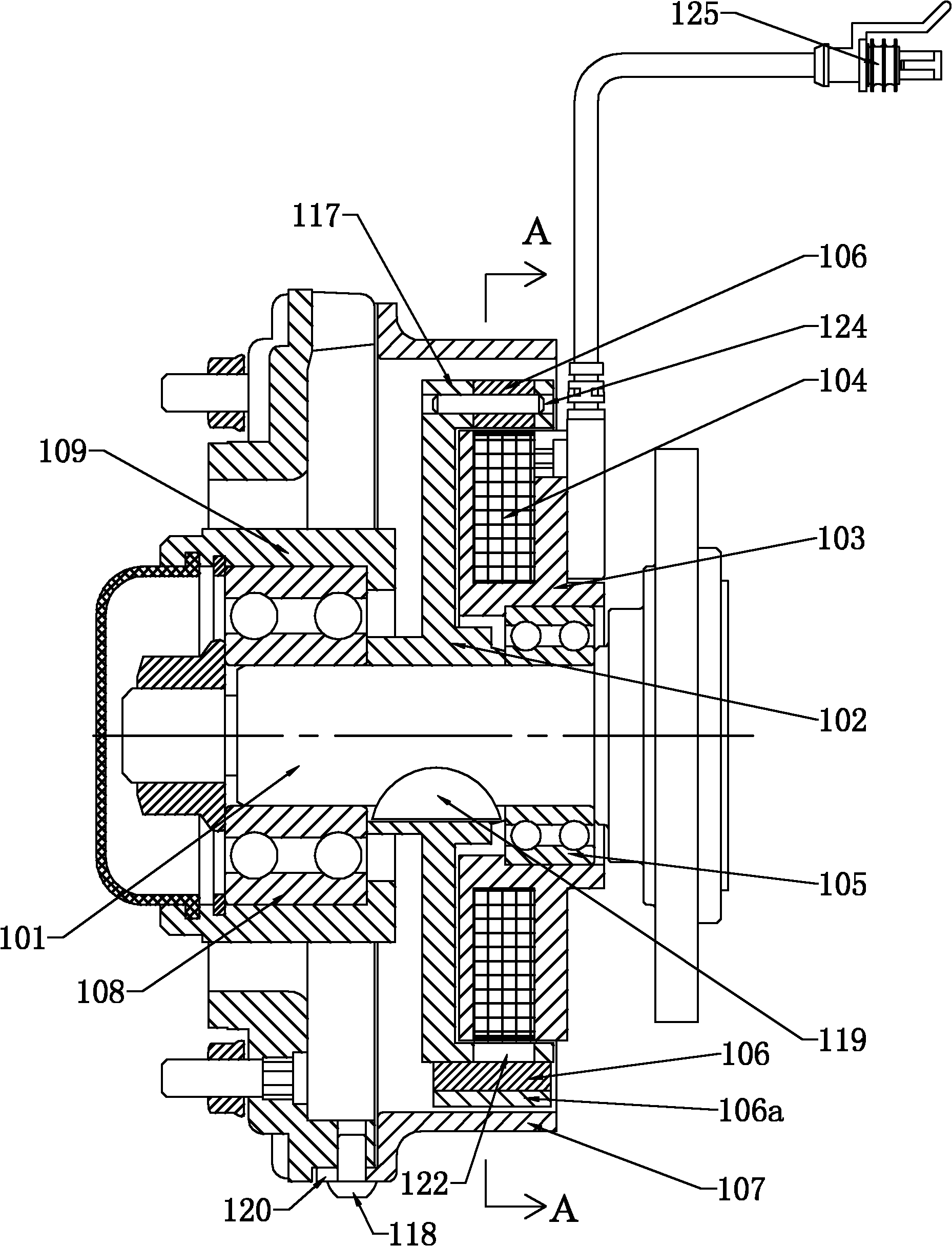
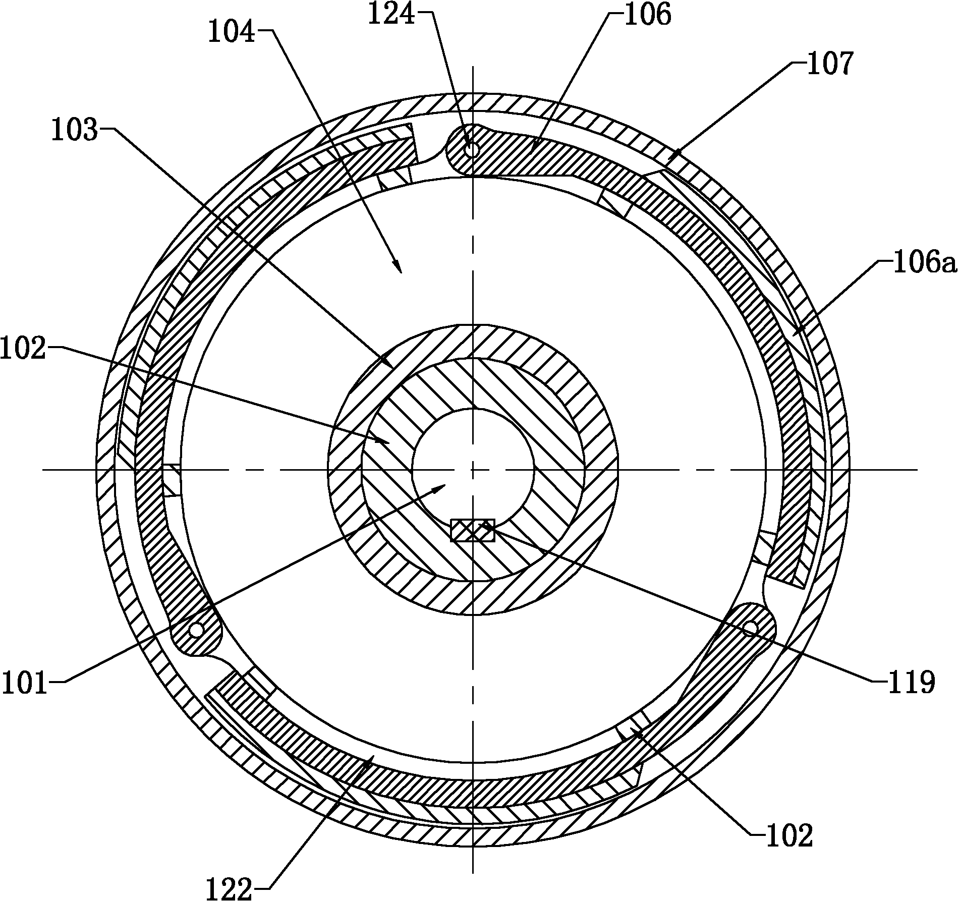
[0062] Such as figure 2 As shown, an electromagnetic transmission device includes a transmission disc 102 (such as Figure 4 shown), also includes the first transmission device, the second transmission device and the first electric control device, such as image 3 , Figure 7 , Figure 8 As shown, wherein the first transmission device comprises three transmission pieces 106, and the three transmission pieces 106 are hinged on the protrusion 117 on the circumferential position of the transmission disc 102 by a pin shaft 124, and the shape of the transmission pieces 106 is arc (such as Figure 5 As shown), the outer surface of the transmission plate 106 is provided with a layer of arc-shaped friction plate 106a bonded on the transmission plate 106 through pressing; the second transmission device is a transmission cylinder 107 (such as Figure 9 , Figure 10 As shown), the transmission cylinder 107 has an opposite end surface with the transmission disk 102 on the outside of ...

Embodiment 2

[0077] Such as Figure 11 shown in Figure 2-10 Under the premise that the other structures in the first embodiment shown in the figure remain unchanged, the difference between the two-speed electromagnetic fan clutch in this embodiment and the first embodiment is that it also includes a magnet fixing plate 210, which is located on the fan The cavity of the fixed disk 209 is installed on the transmission shaft 201 through the transmission sleeve 233. The position of the opposite end surface of the magnet fixed disk 210 and the fan fixed disk 209 is inlaid with a number of first soft irons 215, and the first soft iron 215 is magnetically adsorbed. The permanent magnet 214 and the second soft iron 216 are inlaid on the corresponding position of the permanent magnet 214 on the fan fixing plate 209 .

[0078] Such as Figure 11 As shown, the specific working process of an electromagnetic transmission device of the present invention in a two-speed electromagnetic fan clutch is as...

Embodiment 3

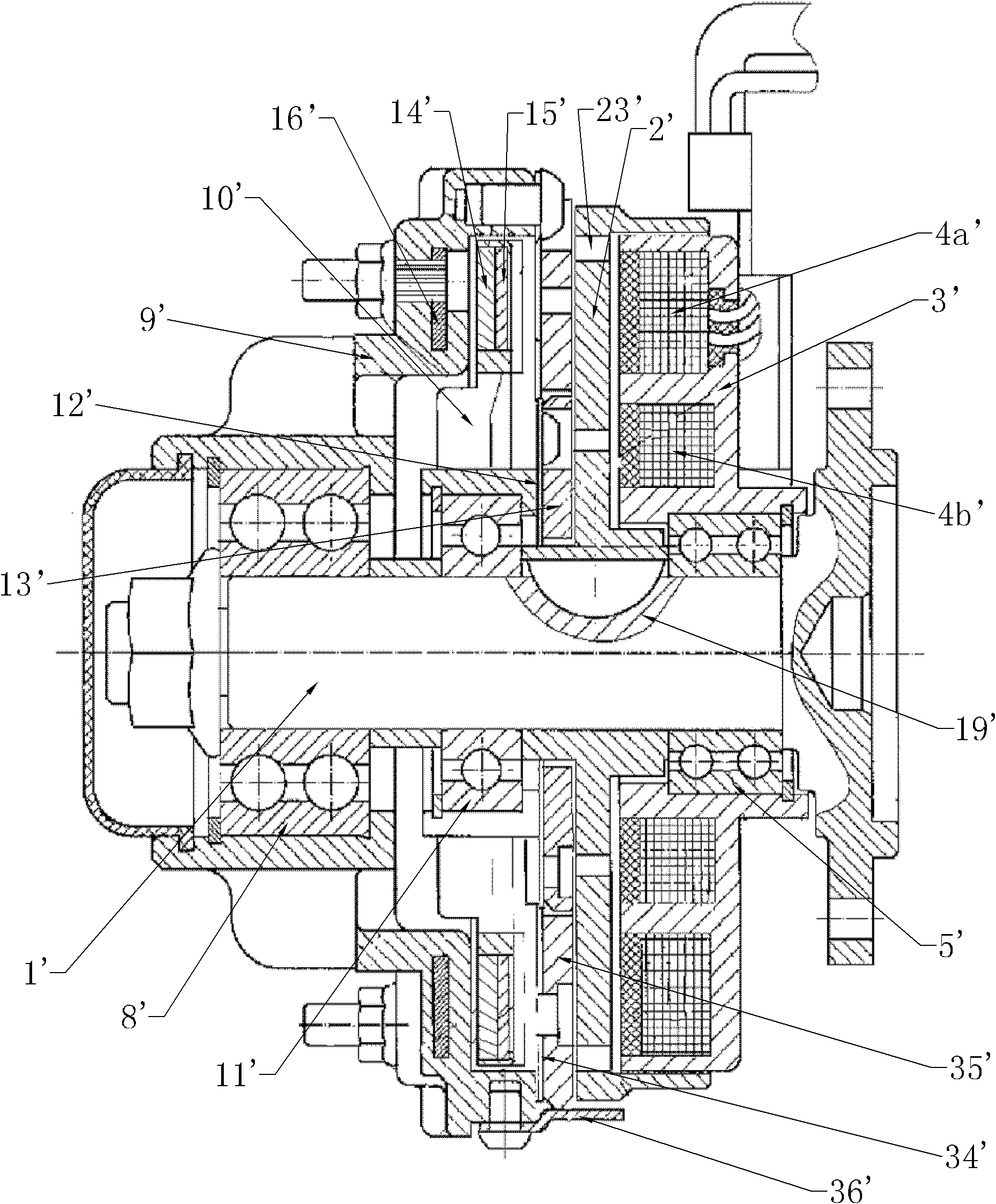
[0087] Such as Figure 12 shown in Figure 11 Under the premise that the other structures in the second embodiment shown in the figure remain unchanged, the difference between the three-speed electromagnetic fan clutch in this embodiment and the first embodiment is that the magnet fixed disk 310 passes through the third bearing 311 (replacing the third bearing 311 in the embodiment The transmission sleeve 233) in the second is installed on the transmission disc 302, and the electromagnet core 303 is provided with inner and outer coil embedding grooves 303a, 303b (such as Figure 15As shown), the outer coil 304a (the first electric control device, which is equivalent to the coil 204 in the second embodiment) is arranged in the outer coil inlay groove 303a, and the direction of the magnetic conduction opening of the outer coil inlay groove 303a points to the circumference of the transmission disc 302 To the position, the inner coil 304b (the second electric control device) is a...


PUM


Abstract

The invention relates to a single-speed electromagnetic fan clutch for cooling an automobile engine, and aims to provide an electromagnetic fan clutch which can lead a fan to run at full speed to cool under the condition that power is switched off suddenly. The electromagnetic fan clutch comprises a transmission shaft, a transmission disc, a fan fixing disc, a first transmission, a second transmission and a first electric control device, the transmission disc is fixedly mounted on the transmission shaft, the fan fixing disc is mounted on the transmission shaft via a first bearing, the second transmission is fixedly connected with the fan fixing disc, and when powered, the first electric control device drives the first transmission to lead the second transmission to be separated from the transmission disc; and when in power failure, the first electric control device drives the first transmission to lead the second transmission to be connected with the transmission disc. The invention further relates to a manufacturing method and a control method for the electromagnetic fan clutch.

Description

technical field [0001] The invention relates to the technical field of vehicle cooling equipment, in particular to a single-speed electromagnetic fan clutch for controlling the rotational speed of a cooling fan of an automobile engine. The present invention also relates to a manufacturing method and a control method of the above-mentioned single-speed electromagnetic fan clutch. Background technique [0002] At present, the electromagnetic fan clutch used in automobiles controls the speed of the fan according to the change of the water temperature of the engine, so as to keep the automobile engine in the best state during operation. Specifically, by controlling the energization or power-off of the coil on the electromagnet core to control the attraction and separation of the suction plate on the magnet fixed plate or the fan fixed plate and the transmission plate, thereby controlling the speed of the fan on the fan fixed plate to achieve The effect of making the fan cool do...

Claims


Application Information

Patent Timeline
Patent Type & Authority Applications(China)
IPC IPC(8): F01P7/04F01P5/14F16D27/01F16D27/02
Inventor 王兆宇邢子义王策
Owner LONGKOU ZHONGYU MACHINERY
Why Eureka
Try Eureka