Two-stage through-flow turbine with ultralow specific speed

A technology of tubular water turbine and specific speed, applied in the direction of reaction engine, hydroelectric power generation, mechanical equipment, etc., can solve the problems of affecting the ventilation effect of cooling towers, unable to meet the requirements of shaft power, affecting the cooling effect of cooling towers, etc. Application prospect and promotion value, effect of radial size reduction and production cost reduction

Inactive Publication Date: 2013-11-27
HOHAI UNIV
View PDF7 Cites 0 Cited by
  • Summary
  • Abstract
  • Description
  • Claims
  • Application Information

AI Technical Summary

Problems solved by technology

According to the flow rate, rotational speed and abundant water head provided by the circulating water of the cooling tower, the unit specific speed converted into the turbine is between 50-60. Type selection between type and Francis type, but because the tail water outlet of the turbine working in this case is pressurized water, and the efficiency of the impact type turbine is too low (generally not high) in the working environment with pressurized tail water 75%), the shaft power cannot meet the requirements, and the nozzles need to be arranged, occupying a large horizontal space, which directly affects the ventilation effect of the cooling tower, and then affects the cooling effect of the cooling tower; although the Francis turbine is specially designed in terms of efficiency, it can Meet the requirements, but because the mixed-flow volute also takes up a lot of horizontal space, it also affects the cooling effect of the cooling tower

Method used


Image

  • Two-stage through-flow turbine with ultralow specific speed
  • Two-stage through-flow turbine with ultralow specific speed
  • Two-stage through-flow turbine with ultralow specific speed

Examples


Embodiment Construction

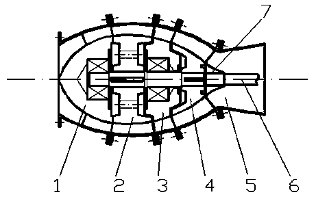
[0059] The double-click tubular ultra-low specific speed turbine designed for a circulating water cooling tower with a capacity of 3,000 tons per hour, a water head of 13 meters, and a speed of 136 rpm has an efficiency of over 85%, which fully meets the requirements of the directly connected cooling fan. required power requirements.

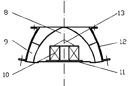
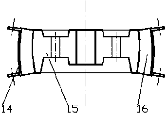
[0060] The appearance of the water turbine is like a spindle, figure 2 The shell (12) of the first guide vane chamber is made of standard carbon steel with a thickness of 10mm and rolled into a circular table-shaped tube with an inner diameter of 580mm in the upper opening and 895.78mm in the lower opening, with a height of 409mm. There are 12 flanges with Φ20mm bolts and light holes. Connect the upper port flange with the water diversion pipe flange through 12 Φ20mm bolts, and connect the lower port flange with the water pipe flange through 12 Φ20mm bolts. image 3 The upper port of the first runner housing (14) is flanged. image 3 The shel...


PUM


Abstract

The invention discloses a two-stage through-flow turbine with ultralow specific speed, which consists of a first guide vane chamber, a first runner chamber, a second guide vane chamber, a second runner chamber, a draft tube and a rotating shaft, wherein the outer shells of the first guide vane chamber, the first runner chamber, the second guide vane chamber, the second runner chamber and the draft tube are integrally connected through bolts; the outer shells of the first guide vane chamber and the second guide vane chamber are welded with one end of a guide vane together, the other end of the guide vane is welded with a flow guide cone together; a bearing is arranged in the flow guide cone to provide the support for the rotating shaft; and the blades of the first runner chamber and the second runner chamber are welded on a hub to form runners with rotating shaft which is connected through keys and form the runner chambers with the outer shells. Pressured water flows through the guide vane in a flow channel of a guide vane area, which is fixed on the outer shell, and then enters a runner area, turns the runner by flushing and drives a shaft system to rotate, in this way, the energy of water flow is converted into the mechanical energy for rotation.

Description

technical field [0001] The invention relates to the technical field of water conservancy machinery, and relates to a device for converting the energy contained in pressurized water flow into rotational mechanical energy, in particular to a two-stage ultra-low specific speed tubular water turbine. Background technique [0002] In petrochemical, smelting and other large and extra-large enterprises, most of them use circulating water cooling towers to reduce the temperature. Due to various reasons, most of the water pumps that provide circulating water for cooling towers have enough head margin. Using this margin to design The power of the water turbine is enough to replace the motor that the cooling tower drives the cooling fan to rotate to achieve the purpose of energy saving. [0003] The internal space of the cooling tower is small, so the water turbine driving the fan should be as small and efficient as possible. According to the flow rate, rotational speed and abundant w...

Claims


Application Information

Patent Timeline
Patent Type & Authority Patents(China)
IPC IPC(8): F03B3/00F03B3/18F03B3/12
CPCY02E10/223Y02E10/20
Inventor 屈波郑源周大庆屈晶钰杨春霞黄敏
Owner HOHAI UNIV
Why Eureka
Try Eureka