
Roller bearing and cage for roller bearing

A technology for rolling bearings and cages, applied in the field of angular contact ball bearings and cages for angular contact ball bearings, which can solve the problems of rolling elements that cannot be fixed by cages, difficulties in the assembly process, etc.

Active Publication Date: 2012-07-04
AB SKF
View PDF6 Cites 6 Cited by
  • Summary
  • Abstract
  • Description
  • Claims
  • Application Information

AI Technical Summary

Problems solved by technology

But the disadvantage is that the rolling elements (such as balls) cannot be fixed by the cage and thus make the assembly process difficult

Method used


Image

  • Roller bearing and cage for roller bearing
  • Roller bearing and cage for roller bearing
  • Roller bearing and cage for roller bearing

Examples


Embodiment Construction

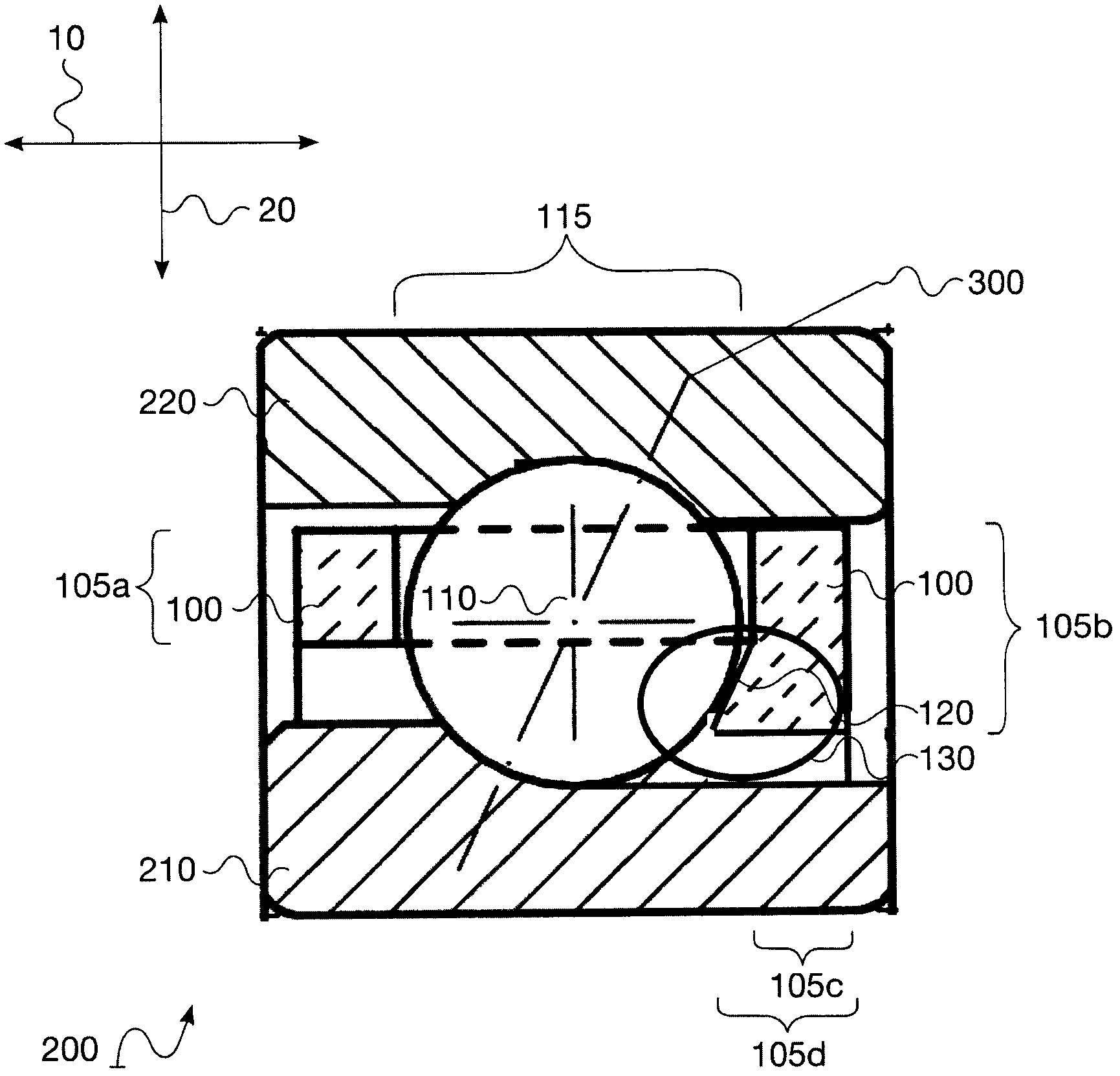
[0018] figure 1 An exemplary embodiment of a rolling bearing 200 is shown. The rolling bearing 200 includes an inner ring 210 and an outer ring 220 . Rolling bearings 200 in figure 1 is designed, for example, as an angular contact ball bearing, as indicated by the tilt axis 300 . Between the inner ring 210 and the outer ring 220 is an embodiment of the rolling elements 110 and the cage 100 . The cage 100 is annular and is designed to accommodate the rolling bodies 110 of the rolling bearing 200 . figure 1 In this respect, a cross section through pocket 115 of cage 100 is shown, arrow 10 indicating the axial direction and arrow 20 specifying the radial direction. also, figure 1 The small rib 120 is shown adjacent to the bearing inner ring 210 . In general, it is also conceivable in other exemplary embodiments that the small rib 120 is adjacent to the bearing outer ring 220 . Examples are not limited to figure 1 on the geometric shape.

[0019] In an embodiment, th...


PUM


Abstract

A roller bearing (200) comprises an inner ring (210), an outer ring (220) and an annular cage (100). The annular cage (100) retains and guides at least one roller body (110) of the roller bearing (200). The annular cage (100) comprises at least one pocket (115) for retaining the roller body (110) and a retaining rim (120) having the roller body (110) at least on one axial end of the pocket (115). The retaining rim (120) extends in the radial direction relative to the cage (100).

Description

technical field [0001] The invention relates to a rolling bearing and a cage for a rolling bearing, in particular an angular contact ball bearing and a cage for an angular contact ball bearing. Background technique [0002] as image 3 As shown in the sectional view of the medium angular contact ball bearing, a conventional rolling bearing 350 is composed of an inner ring 360 , an outer ring 370 and rolling elements 390 , wherein the rolling elements are guided by a cage 380 . For example, balls, cones, cylinders etc. are used as rolling bodies in this respect. Let's take ball bearings as an example. also, image 3 Roller bearing 350 is shown in the form of an angular contact ball bearing, as indicated by tilt axis 400 . The holder 380 has multiple functions. For guiding the rolling bodies, the cage has recesses or pockets 410 into which the rolling bodies can be inserted. Thus, on the one hand, the cage guides the rolling elements 390 into the pockets 410 designed for t...

Claims


Application Information

Patent Timeline
Patent Type & Authority Applications(China)
IPC IPC(8): F16C33/38F16C43/04
CPCF16C33/3887F16C33/3843F16C19/163F16C43/06F16C2300/02F16C2240/40Y10T29/49643Y10T29/49691B21D53/12
Inventor A·吉尔伯特-西蒙H·豪克T·西格H·赫布斯特S·卡姆
Owner AB SKF
Features
  • Generate Ideas
  • Intellectual Property
  • Life Sciences
  • Materials
  • Tech Scout
  • Unparalleled Data Quality
  • Higher Quality Content
  • 60% Fewer Hallucinations
Learn More