Three-way valve with electromagnetic pilot sliding valve for air-conditioner water heater

A technology for air-conditioning water heaters and pilot valves, which is applied to multi-port valves, valve operation/release devices, valve details, etc., can solve problems such as large current consumption, burnt engineering plastic sliding valve blocks, and inability to seal, achieve switching and Reliable sealing performance, avoiding scalding and damage accidents, and switching the effect of sufficient thrust

Inactive Publication Date: 2012-07-04
陈则韶
View PDF3 Cites 12 Cited by
  • Summary
  • Abstract
  • Description
  • Claims
  • Application Information

AI Technical Summary

Problems solved by technology

At present, the multi-circulation circuit switching of multi-functional air-conditioning water heaters uses two two-position solenoid valves to replace the function of a three-way valve in addition to the four-way valve combination. Generally, the diameter of the solenoid valve should not be too large, otherwise the solenoid coil will be large and consume High current, high cost
The applicant once transformed the four-way valve into a three-way valve. However, in the transformation, it was necessary to weld the unused pipe joints of the four-way valve and to modify the auxiliary gas path, which often made the engineering plastic sliding valve block of the four-way valve Burnt and cannot be sealed

Method used


Image

  • Three-way valve with electromagnetic pilot sliding valve for air-conditioner water heater
  • Three-way valve with electromagnetic pilot sliding valve for air-conditioner water heater
  • Three-way valve with electromagnetic pilot sliding valve for air-conditioner water heater

Examples


Embodiment 1

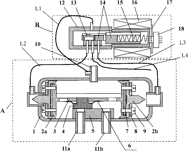
[0030] The structure and working principle of the three-way valve with electromagnetic pilot slide valve for a kind of air-conditioning water heater of embodiment 1, respectively by figure 1 , 2 , 3, and 4 jointly illustrate that embodiment 1 adopts a gas distribution valve block structure that moves in a plane.

[0031] Such as figure 1 As shown, a three-way valve with an electromagnetic pilot slide valve for an air-conditioning water heater in Embodiment 1 includes the main slide valve shown in the dotted line frame A, the electromagnetic pilot slide valve shown in the dotted line frame B, and the electromagnetic coil 16. The electromagnetic pilot spool valve includes a pilot valve body 12, a pilot valve core 14, a return spring 15, and a sliding diversion cap 13; the left part of the pilot valve body is the air distribution chamber section, and the right part is There are four capillary tubes outside the sliding hole section and the air distribution chamber section, the u...

Embodiment 2

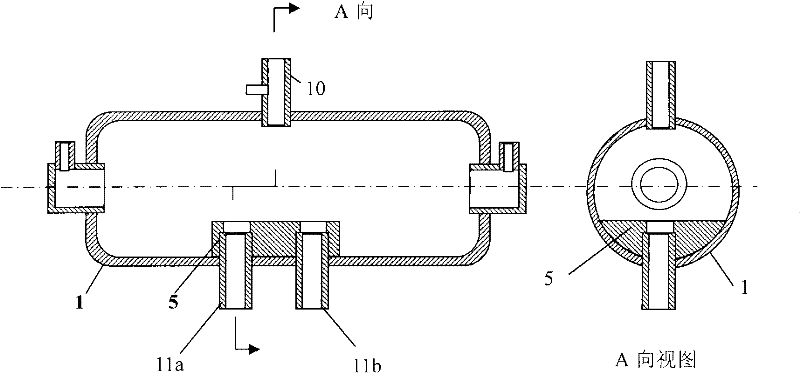
[0033] The structure and working principle of the three-way valve with electromagnetic pilot slide valve for a kind of air-conditioning water heater of embodiment 2, respectively by Figure 5 , 7 , 8, and 9 jointly illustrate that Embodiment 2 adopts a gas distribution valve plug structure.

[0034] Such as Figure 5 As shown, a three-way valve with an electromagnetic pilot slide valve for an air-conditioning water heater in Embodiment 2 includes the main slide valve shown in the dotted line box A, and the electromagnetic pilot slide valve and electromagnetic pilot slide valve shown in the dotted line box B. The coil 16; the structure and working principle of the electromagnetic pilot slide valve are completely the same as those of Embodiment 1.

[0035] The main slide valve of said embodiment 2 mainly includes a cylindrical main valve body 1, two pistons 2a, 2b, two valve plugs 4a, 4b, and a plate-shaped piston rod 3, see Figure 5 ; The two ends of the plate-shaped piston...

Embodiment 3

[0038] The structure and working principle of the three-way valve with electromagnetic pilot slide valve for a kind of air-conditioning water heater of embodiment 3, respectively by Image 6 , 7 , 8, and 9 jointly illustrate that Embodiment 2 adopts a gas distribution valve plug structure.

[0039] Such as Image 6 As shown, a three-way valve with an electromagnetic pilot slide valve for an air-conditioning water heater in Embodiment 3 includes the main slide valve shown in the dotted line box A, and the electromagnetic pilot slide valve and electromagnetic pilot slide valve shown in the dotted line box B. The coil 16; the structure and working principle of the electromagnetic pilot slide valve are completely the same as those of Embodiment 1.

[0040] The main slide valve of said embodiment 3 mainly includes a cylindrical main valve body 1, two pistons 2a, 2b, two valve plugs 4a, 4b, a plate-shaped piston rod 3, two tension springs 19a, 19b, see Figure 5 ; The two ends o...


PUM


Abstract

The invention discloses a three-way valve with an electromagnetic pilot sliding valve for an air-conditioner water heater. According to the technical scheme, the three-way valve comprises a main sliding valve, the electromagnetic pilot sliding valve and an electromagnetic coil, wherein the electromagnetic pilot sliding valve comprises a pilot valve body, a pilot valve core, a restoring spring, a sliding diversion cap, an air inlet capillary, a left capillary, a middle capillary and a right capillary. The three-way valve is characterized in that: the main sliding valve comprises a main valve body, pistons, a plate-like piston rod, an air distribution valve block and a spring sheet; two pistons connected with the plate-like piston rod partitions the cavity of the main valve body into a left air chamber, a middle air chamber and a right air chamber; the middle air chamber is provided with an air inlet pipe joint and two air outlet pipe joints connected to double holes of a valve seat; the left and right capillaries are connected with the left and right air chambers of the main valve body, the air inlet capillary is connected with a branch pipe of the air inlet pipe joint, and one end of the middle capillary is open and connected with a low-pressure pipeline of a refrigerating loop; and the position of the pilot valve core and the pressure of the left and right air chambers of the main valve body are changed by power-on and power-off of the electromagnetic coil, so that the pistons and the plate-like piston rod shift, the orifice of an air distribution valve block sealing cover is changed and an air outlet passage is switched.

Description

technical field [0001] The invention relates to the field of valves and the control field of air-conditioning heat pump water heaters. Background technique [0002] In recent years, due to the demand for energy saving, the development of multifunctional air-conditioning water heaters has become a hot topic. It is necessary to change the cooling and heating air conditioners from two cycles of cooling and heating to four cycles of cooling, heating, cooling and hot water, and hot water. Additional The five cycles of defrosting are difficult to complete only by using four-way valve switching, and a three-way valve suitable for switching refrigerant circuits is urgently needed. The applicant has paid attention to it for 10 years, and the market has not developed a suitable three-way valve. After consulting 504 abstracts of inventions and invention patents related to three-way valves, there is no suitable three-way valve for multi-functional air-conditioning water heaters. . At ...

Claims


Application Information

Patent Timeline
Patent Type & Authority Applications(China)
IPC IPC(8): F16K11/065F16K31/122F16K31/06
Inventor 陈则韶陈宏文
Owner 陈则韶
Why Eureka
Try Eureka