

Displacement sensor width measuring method achieved by adopting finite state machine
A technology of displacement sensor and finite state machine, which is applied in the direction of measuring devices, electrical devices, instruments, etc., can solve the problems of the displacement sensor width measurement method, such as the influence of mechanical processing vibration, to achieve accurate measurement, reduce harsh requirements, and shield error signals Effect
Active Publication Date: 2014-04-30
NO 11 INST OF NO 6 ACADEMY OF CHINA AEROSPACE SCI & TECH
View PDF4 Cites 0 Cited by
- Summary
- Abstract
- Description
- Claims
- Application Information
AI Technical Summary
Problems solved by technology
[0003] The purpose of the present invention is to provide a displacement sensor width measurement method implemented by a finite state machine, which solves the technical problem that the existing displacement sensor width measurement method is affected by machining and vibration
Method used
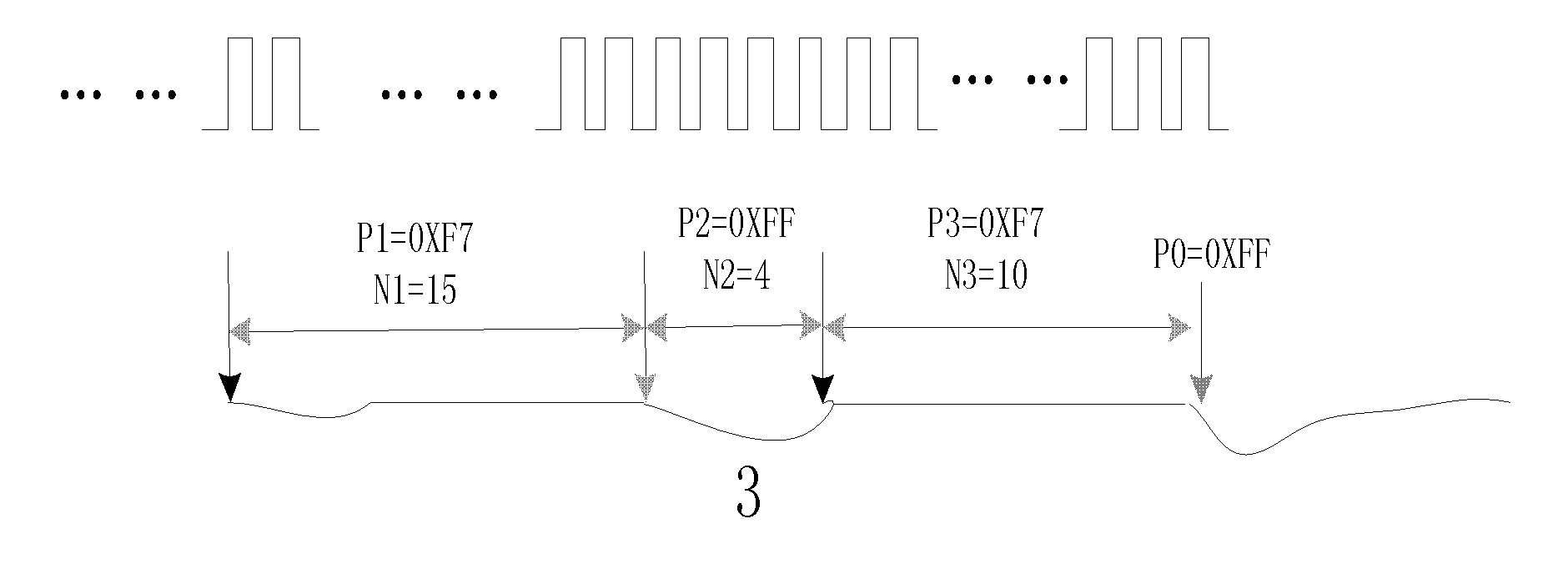
View moreImage
Smart ImageViewing Examples

Examples
Embodiment
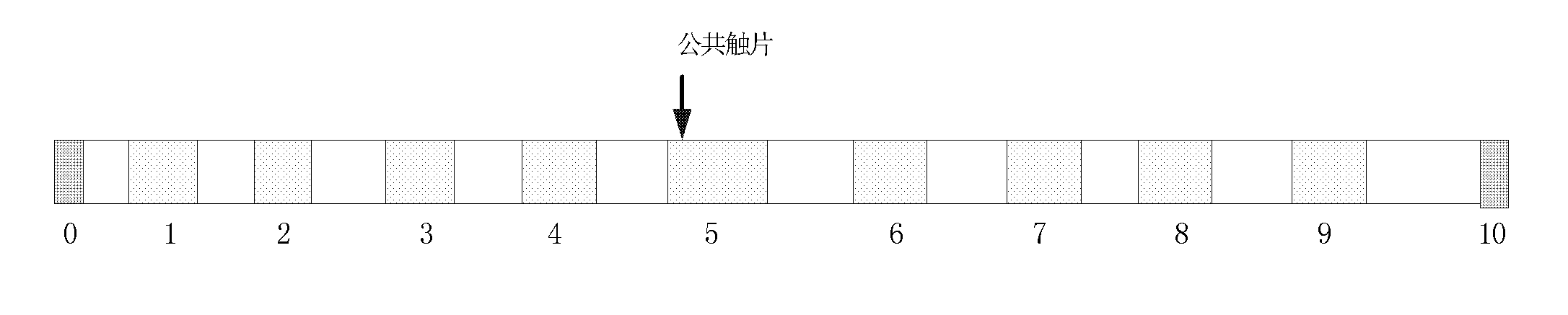
[0048] Such as figure 1 As shown, 0 to 10 are the metal contacts of the sensor guide, which correspond to the D0-D10 digits of the digital signal, among which 0 and 10 are the test start point and test end point respectively, and the insulation area is between each metal contact. The definition adopts 16-bit data and defines the unused bits as the state "1". to "1".
Login to View More PUM
 Abstract
The invention relates to a displacement sensor width measuring method achieved by adopting a finite state machine. The method comprises the following steps of: (1) confirming a conduction area; (2) confirming a test starting point and a test ending point; (3) building data state machine models; and (4) using the data state machine models to accomplish the width measurement of the sensor. The method disclosed by the invention solves the technical problem that an existing displacement sensor width measuring method is affected by mechanical process and vibrations. The method disclosed by the invention adopts the measuring method with eight data state machine models to analyze and judge a digital pulse value in each state, so as to accurately measure the displacement sensor and precisely position the positions.
Description
technical field [0001] The invention is a digital signal detection method, which can be used for pulse width measurement of a displacement sensor and digital signal state measurement. Background technique [0002] In aerospace engines, the built-in displacement sensor of the regulator is often used to measure and judge the valve opening. This displacement sensor is different from the conventional displacement sensor. It is a mechanical point-surface contact structure. The sensor width and state use pulse width and different data states. bit representation. This type of displacement sensor has the characteristics of high precision, relatively small measurement range, and close cooperation with the valve. By using electric pulse measurement and correctly determining the position of the sensor and realizing accurate positioning together with the actuator, the measurement accuracy directly affects The state of the valve affects the working performance of the engine, so the sens...
Claims
Login to View More Application Information
Patent Timeline
 Patent Type & Authority Patents(China)
IPC IPC(8): G01B7/02
Inventor 刘军韩童珉
Owner NO 11 INST OF NO 6 ACADEMY OF CHINA AEROSPACE SCI & TECH