
Low altitude photography image control point arranging method

A photographic image and low-altitude technology, which is applied in the field of low-altitude photographic image control point layout, can solve the problems of reducing the coordinate and elevation accuracy of aerial surveys, affecting the coordinate accuracy of image control points, and being unable to arrange freely, so as to improve triangulation and mapping. Accuracy, flexible layout, and the effect of improving the freedom of layout

Active Publication Date: 2015-05-06
CENT SOUTHERN CHINA ELECTRIC POWER DESIGN INST CHINA POWER ENG CONSULTING GROUP CORP
View PDF1 Cites 0 Cited by
  • Summary
  • Abstract
  • Description
  • Claims
  • Application Information

AI Technical Summary

Problems solved by technology

[0002] At present, the low-altitude digital photography of UAVs has a small image size and many photos. The layout of the image control points is implemented in accordance with the current specification requirements. The first and last pair of image control points should be perpendicular to the flight line. This method is difficult to operate and cannot be freely arranged. For dense vegetation, wasteland, deserts and other areas without obvious feature points, it is very difficult to puncture points, and sometimes it is impossible to puncture points, even if the features can be found point, the specific location of the image is also very inaccurate, which affects the coordinate accuracy of the image control point, thereby reducing the accuracy of the aerial survey office coordinates and elevation

Method used


Image

  • Low altitude photography image control point arranging method

Examples


Embodiment Construction

[0013] Below in conjunction with accompanying drawing and specific embodiment the present invention is described in further detail:

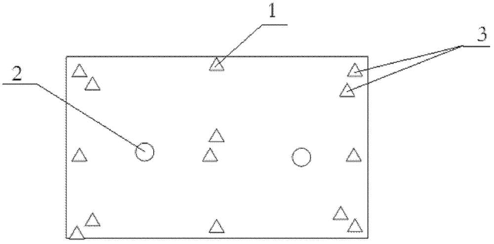
[0014] Layout method of low-altitude photographic image control points According to the aerial photography area map, formulate the layout model in the aerial photography area network and arrange the control points, refer to figure 1 As shown, the plane control point 1 is arranged around the aerial photography area, the length of the photographic baseline is b, the span of the course spacing is 6-8b when the high-precision encrypted points are located, and the span of the lateral spacing is 4b. For the image control points, the elevation control points 2 are arranged in a lock shape, and the interval of elevation control points along the lateral direction is 4b, and the span along the course is 6-8b.

[0015] Set up landmarks before the flight. According to the map of the aerial photography area, formulate a labeling plan in the area that needs a...


PUM


Abstract

The invention relates to the technical field of electrical power engineering survey, belongs to the field of surveying and mapping and particularly relates to a low altitude photography image control point arranging method. According to an aerial photographic regional map, a mark distribution model is established and control mark points are arranged in an aerial photographic regional network; plane control points are arranged around an aerial photographic region; the length of a photographic baseline is b; in the process of encrypting point positions under high precision, the span of the heading spacing is in the range of 6 to 8b and the span of the lateral spacing is 4b; a pair of image control points are respectively arranged at both ends of each route; vertical control points are arranged into a lock shape; the spans of the vertical control points along the lateral spacing are 4b and the spans of the vertical control points along the heading spacing is 6 to 8b; and when plane point positions are encrypted under high precision, the vertical control points are arranged. According to the invention, the aerial triangulation and mapping accuracy of the photogrammetric office work is improved, the surveying and mapping production efficiency is improved, the points are flexibly distributed under the condition that the requirement on the precision of the photogrammetric office work is met; the number of the arranged field image control points is reduced; and the low altitude photography image control point arranging method is suitable for low altitude photographic surveying in any land area.

Description

technical field [0001] The invention relates to the technical field of electric power engineering survey, belongs to the field of surveying and mapping science and technology, and in particular relates to a method for laying out low-altitude photographic image control points. Background technique [0002] At present, the low-altitude digital photography of UAVs has a small image size and many photos. The layout of the image control points is implemented in accordance with the current specification requirements. The first and last pair of image control points should be perpendicular to the flight line. This method is difficult to operate and cannot be freely arranged. For dense vegetation, wasteland, desert and other areas without obvious feature points, it is very difficult to puncture points, and sometimes it is impossible to puncture points, even if the features can be found It is also very inaccurate to judge the specific position of the image, thus affecting the coordina...

Claims


Application Information

Patent Timeline
Patent Type & Authority Patents(China)
IPC IPC(8): G01C15/02G01C11/00
Inventor 胡吉伦胡庆武程正逢王圣祖高福山
Owner CENT SOUTHERN CHINA ELECTRIC POWER DESIGN INST CHINA POWER ENG CONSULTING GROUP CORP
Learn More