Liquid crystal display device

A technology for liquid crystal display devices and display areas, applied to static indicators, instruments, etc., can solve the problems of increasing product costs, increasing wiring development costs, and inability to use driver chips, so as to reduce development costs, reduce mold opening costs, and avoid The effect of repeating the design

Active Publication Date: 2012-07-04
SHANGHAI TIANMA MICRO ELECTRONICS CO LTD
View PDF5 Cites 28 Cited by
  • Summary
  • Abstract
  • Description
  • Claims
  • Application Information

AI Technical Summary

Problems solved by technology

[0007] However, the above-mentioned liquid crystal display device has the following problems: the data line connection line and the scanning connection line connected to the driver chip are interleaved, and such repeated design increases the development cost of wiring: further, the prior art is not In the driver chip of the narrow-frame liquid crystal display device, the pin of the data line is located in the middle, and the pins connected to the scan line are located on both sides of the data line pin, so the narrow-frame liquid crystal display device cannot use the driver chip in the prior art, and needs Redesign the corresponding driver chip, which increases the cost of the product

Method used


Image

  • Liquid crystal display device
  • Liquid crystal display device
  • Liquid crystal display device

Examples


Embodiment Construction

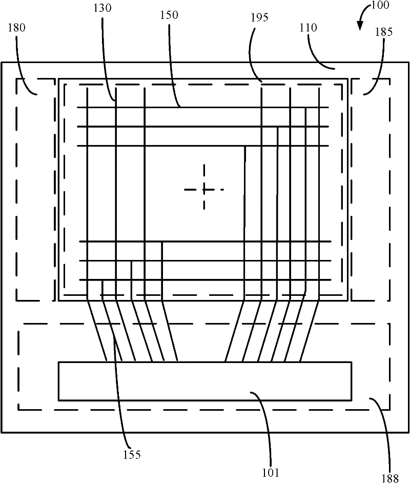
[0029] Such as figure 1 As shown, the inventors found that the driver chips must be designed to be interleaved with data line drivers and scan line drivers. Such repeated designs increase the development cost of wiring. In the prior art, most of the driver chips are designed with scan line driver chip pins on both sides and data line driver chip pins in the middle. figure 1 The driver chip of the narrow-frame liquid crystal display device needs to increase the development of a new driver chip, which increases the product cost.

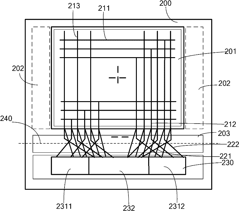
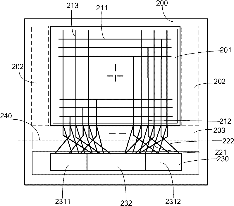
[0030] In order to solve the problems in the prior art, the inventor of the present invention provides a liquid crystal display device, comprising:

[0031] An array substrate and a color filter substrate oppositely arranged, the array substrate is divided into a display area, a driver chip and a frame area, and the frame area includes a first frame area located on both sides of the display area and a second frame area located between the display area...


PUM


Abstract

The invention provides a liquid crystal display device. The liquid crystal display device comprises an array substrate and a colorful film substrate which is opposite to the array substrate; the array substrate is divided into a display area, a drive chip and a frame area; the display area comprises a plurality of scanning lines and a plurality of data lines; the drive chip comprises a data line drive part and scanning line drive parts; the data line drive part is connected with the data lines; the scanning line drive parts are used for being connected with the scanning lines; one part of the frame area comprises data line connection areas and scanning line connection areas; and the scanning line connection areas are positioned on two sides of each data line connection area. The scanning line connection areas are positioned on two sides of each data line connection area, so the repeated design that the scanning lines and the data lines are staggered is reduced, and design cost is reduced; and furthermore, the corresponding drive chip is compatible with the drive chip in the prior art, and mould opening cost is reduced.

Description

technical field [0001] The invention relates to a liquid crystal display panel, in particular to a liquid crystal display device which reduces the frame width of the liquid crystal display panel to achieve a narrow frame design. Background technique [0002] Flat-panel displays are currently the most popular displays, among which liquid crystal displays are widely used in electronic products such as computer screens, mobile phones, personal digital assistants, and flat-screen TVs because of their thin and light appearance, power saving, and no radiation. [0003] Please refer to figure 1 , is a structural schematic diagram of a narrow-frame liquid crystal display device 100 in the prior art, including an array substrate 110 and a color filter substrate (not shown), and the liquid crystal molecular layer is sandwiched between the array substrate 110 and the color filter substrate. The color filter substrate is a color filter for displaying a color picture. The array substra...

Claims


Application Information

Patent Timeline
IPC IPC(8): G02F1/133G09G3/36
Inventor 黄贤军
Owner SHANGHAI TIANMA MICRO ELECTRONICS CO LTD
Why Eureka
Try Eureka