Method for rapidly analyzing energy distribution of train

A technology for rapid analysis and energy distribution, applied in the fields of motor vehicles, electric vehicles, power management, etc., which can solve the problems of lengthening the design cycle, unpredictable energy absorption status of energy absorption devices, and increasing design costs.

Inactive Publication Date: 2012-07-04
CRRC CHANGCHUN RAILWAY VEHICLES CO LTD
View PDF4 Cites 9 Cited by
  • Summary
  • Abstract
  • Description
  • Claims
  • Application Information

AI Technical Summary

Problems solved by technology

[0003] Due to the limitation of models and computer hardware conditions, domestic train collision energy absorption analysis mostly adopts single-section vehicle with driver's cab collision rigid wall for front-end energy absorption research, reflecting the energy absorption of vehicle end structures, and it is impossible to predict the energy absorption of energy-absorbing devices between vehicles Energy status, the calculation of energy allocation in the early stage of national highway bus design is mostly monopolized by the American OLEO company, which uses its own internally developed software for calculation. The disadvantages of this cooperation method are that the communication and information feedback are not timely, delaying the design progress and increasing the design cost; The simulation engineers of domestic rail car manufacturers also try to use the train finite element marshalling model for simulation, which will also bring a lot of calculation time. Each calculation requires hundreds of hours, prolonging the design cycle and increasing the design cost.

Method used


Image

  • Method for rapidly analyzing energy distribution of train
  • Method for rapidly analyzing energy distribution of train
  • Method for rapidly analyzing energy distribution of train

Examples


Embodiment Construction

[0028] refer to figure 1 , the inventive method comprises the following steps:

[0029] 101) Model building

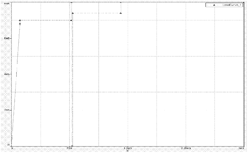
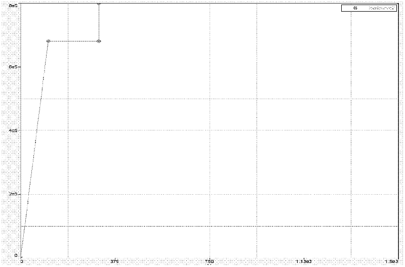
[0030] Establish the rigid model of the train car body through the HYPERMESH software, constrain the direction of movement of the car body and the equivalent weight of the train through the material model, and only allow longitudinal and vertical movement along the car body, and establish the model of the coupler buffer and crush tube through the nonlinear spring unit , drive the movement of the buffer and the crush tube through the force-travel curve properties of the spring material, and establish the equivalent wheel-rail model. The degree of freedom of the wheel-rail model is fully constrained. The information of the model is completed to complete the establishment of the train model.

[0031] 6 marshalling models, the moving car weighs 35 tons, the trailer weighs 33 tons, the movement mode of the train model is to move only along the longitudinal degree of freed...


PUM


Abstract

The invention relates to a method for rapidly analyzing the energy distribution of a train. The method comprises the following steps of: establishing a vehicle body rigidity model, a vehicle coupler buffering device model and a wheel track model by utilizing HYPERMESH software, wherein the wheel track model comprises vehicle body weight information, a vehicle body material freedom degree state, model unit information, parking brake information and operating wheel track information; applying a train dead weight which comprises gravity accelerations of the moving train and the static train; establishing a relation of contact which comprises moving train internal contact, static train internal contact, moving train and static train contact and wheel track contact; defining an initial collision speed; defining output information; outputting a calculating file and submitting the calculating file to an LS-DYNA platform to calculate; and reading information of a calculating result, carrying out analysis judgment according to the calculating result, finishing analysis if the design requirement is met, or returning to the step (101) to modify design parameters to recalculate. According to the invention, the analysis on the energy distribution can be rapidly implemented, the establishment of the models is completed in 8 hours, and the calculation for once is completed in ten minutes.

Description

technical field [0001] The invention relates to the field of train passive safety analysis, in particular to a method for quickly realizing the energy distribution of the vehicle end in the early stage of rail passenger vehicle design. Background technique [0002] With the improvement of train speed and operating efficiency, collision accidents occur frequently during the operation of trains, and people pay more and more attention to them. The occurrence of train collision accidents not only threatens the lives of passengers, but also has huge economic losses and reputational impacts. With the 7.23 high-speed train rear-end collision accident and the Shanghai subway rear-end collision accident, it shows that even if active protection measures such as advanced signaling, dispatch management, and program management are adopted, train collision accidents are still inevitable. Therefore, it is worthy of our in-depth study to do a good job in passive safety protection to protect...

Claims


Application Information

Patent Timeline
IPC IPC(8): G06F17/50
CPCG06F17/50G06F2217/78B60Y2304/00B60W10/26B60L3/0007B60L2200/26B60L2200/30B60L2240/12B60L2240/14B60L2240/26B60L2240/30B60L2240/465B60L2240/64B60L2240/80B60L2250/00B60L2260/44G06F2119/06Y02T10/72Y02T90/16
Inventor 李本怀
Owner CRRC CHANGCHUN RAILWAY VEHICLES CO LTD
Why Eureka
Try Eureka