Terminal insertion device and terminal insertion method

A terminal insertion device and terminal technology, which is applied in the direction of coupling device, connecting device components, and contact assembly/disassembly, etc., can solve the problems of unable to insert the terminal smoothly, interfere with the upper and lower ends of the opening, etc., so as to prevent the reduction of productivity. , the effect of improving the insertion accuracy

Active Publication Date: 2012-07-04
YAZAKI CORP
View PDF8 Cites 7 Cited by
  • Summary
  • Abstract
  • Description
  • Claims
  • Application Information

AI Technical Summary

Problems solved by technology

Since the terminal 4 1 、4 2 A change of form will occur for each terminal 4 1 、4 2 The front end 4b of the connector housing interferes with the upper and lower ends of the opening of the terminal accommodation chamber of the connector housing, making it impossible to insert each terminal smoothly

Method used


Image

  • Terminal insertion device and terminal insertion method
  • Terminal insertion device and terminal insertion method
  • Terminal insertion device and terminal insertion method

Examples


Embodiment Construction

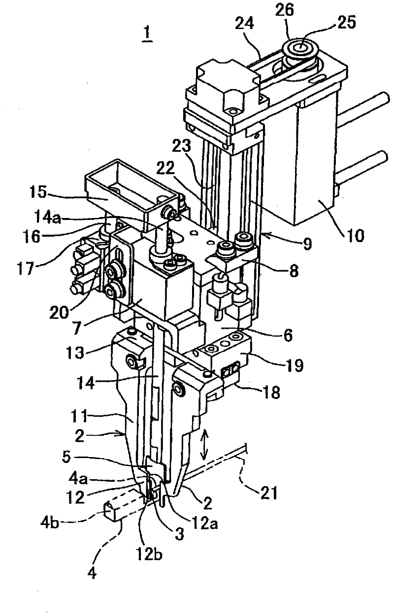
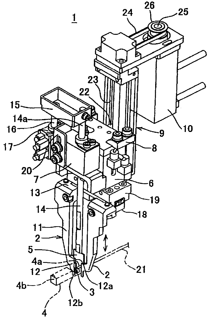
[0037] figure 1 It is a figure which shows one Embodiment of the terminal insertion apparatus and terminal insertion method of this invention.

[0038] The terminal insertion device 1 has: a pair of left and right terminal buckles 2; a terminal pressing member 5 that pushes the terminal 4 against the upper side of the horizontal protrusion 3 at the lower end of the terminal buckles 2; opens and closes the pair of terminal buckles 2 The pneumatic chuck cylinder 6; the cylinder 7 for lifting and lowering the terminal pressing member 5; the block part 8 for fixing the air chuck cylinder 6 and the cylinder 7; A rail-shaped vertical adjustment guide 9; and a servo motor (motor) 10 that drives the block portion 8 to move up and down along the vertical adjustment guide 9.

[0039] On at least one of the pair of terminal hooks 2 , preferably on both, a horizontal protruding portion 3 facing inward is provided. A pair of terminal buckles 2 are located on the left and right facing ea...


PUM


Abstract

Even when the position of a core wire crimping part of a terminal on each terminal vertically deflects relative to a wire center of an electrified wire terminal, the terminal can be smoothly and reliably inserted into a connector housing. A terminal insertion device (1) is provided and comprises the following components: a pair of left-and-right terminal buckles (2) which is provided with an inward projection (3) for supporting the terminal and is used for terminal insertion; a terminal pressing component (5) which pushes the core wire crimping part (4a) of an electrified wire terminal (4) on the projection (3); a measuring mechanism (17) which is used for measuring the height of the core wire crimping part relative to the center of the wire (21); a vertical adjustment guide support (9) which integrally lift the terminal buckle and the terminal pressing component according to a measuring result for correcting vertical inclination of the terminal; and a motor (10). The measuring mechanism (17) measures the height of the core wire pressing part relative to the wire center in a state that the terminal pressing component (5) presses the core wire crimping part (4a) on the projection (3) from upper part.

Description

technical field [0001] The invention relates to a terminal insertion device and a terminal insertion method for holding a terminal with electric wires by a chuck and inserting the terminal into a connector housing. Background technique [0002] Conventionally, various terminal insertion devices and terminal insertion methods have been proposed in order to insert live wire terminals into insulating connector housings. [0003] For example, in Patent Document 1, it is described that using a pair of terminal guide claws having an inclined guide surface, in order to align the live wire terminal held by the chuck claws with the center of the guide surface, keep the terminal inclined, or adjust the The height of the insertion head including the chuck jaws (not shown). [0004] In addition, in Patent Document 2, it is described that the live wire terminal is clamped from the left and right directions by chuck claws having an L-shaped lower end portion, and a terminal holding plate...

Claims


Application Information

Patent Timeline
Patent Type & Authority Applications(China)
IPC IPC(8): H01R13/428H01R43/20
Inventor 野本喜昭水野晶博中沢雄平浅井淳治大平伦之高田和彦
Owner YAZAKI CORP
Why Eureka
Try Eureka