Clamp ring, cable screw connection and method for assembling a cable screw connection

A technology for cable glands and clamping rings, which is applied to cable terminals, clamping/spring connections, parts of connection devices, etc., and can solve problems such as uncertain loosening torque, loosening of cable glands, laborious inspection, etc.

Active Publication Date: 2012-07-04
TE CONNECTIVITY GERMANY GMBH
View PDF5 Cites 13 Cited by
  • Summary
  • Abstract
  • Description
  • Claims
  • Application Information

AI Technical Summary

Problems solved by technology

This has the disadvantage that any inspections undertaken for proper installation will be laborious and require specialized tools
In addition, it

Method used


Image

  • Clamp ring, cable screw connection and method for assembling a cable screw connection
  • Clamp ring, cable screw connection and method for assembling a cable screw connection
  • Clamp ring, cable screw connection and method for assembling a cable screw connection

Examples


Embodiment Construction

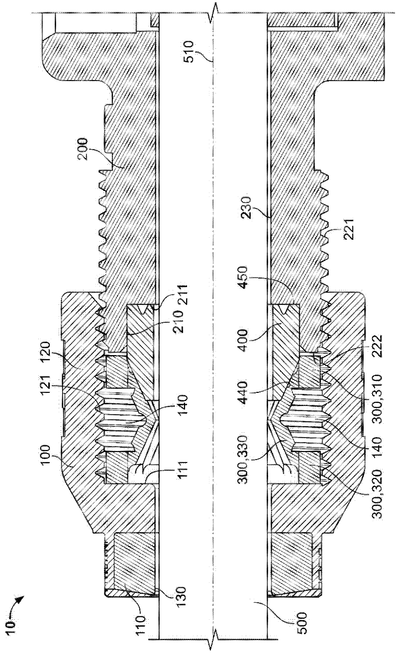
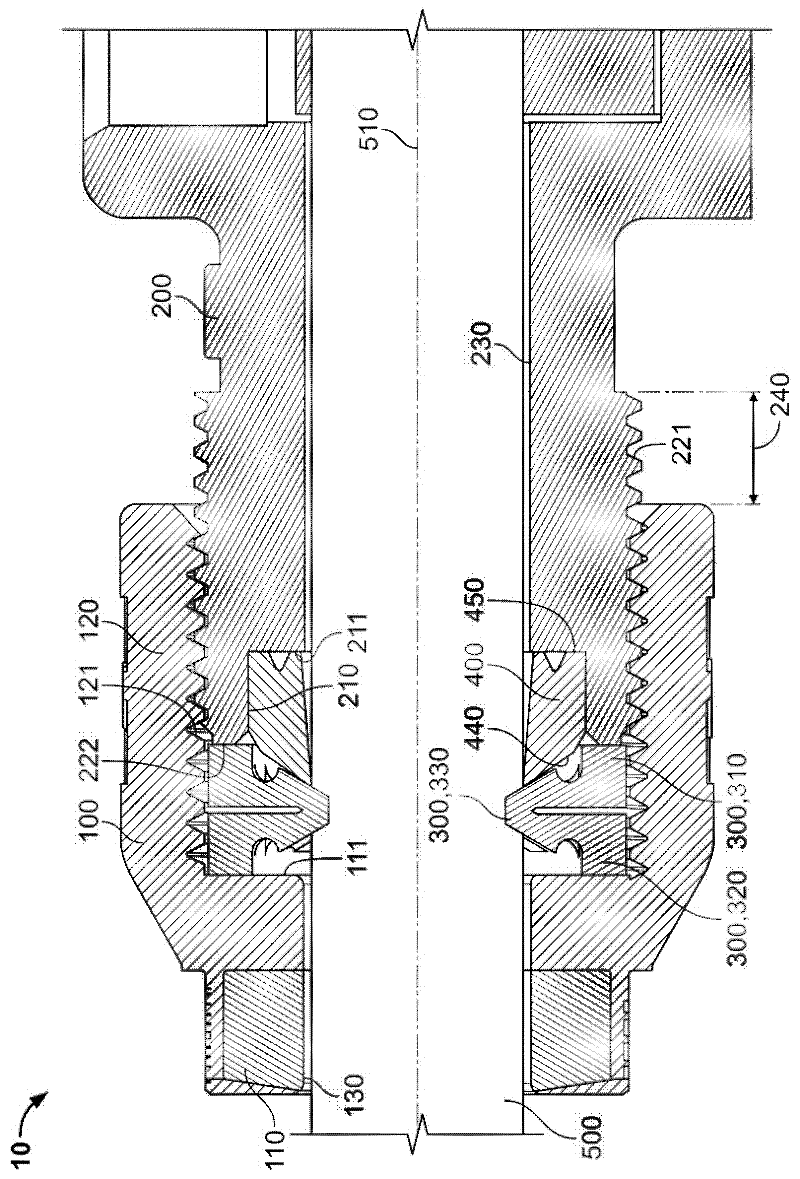
[0022] figure 1 A section through the cable gland 10 partially screwed onto the counterpart part 200 is shown somewhat schematically. The counter part 200 may be, for example, a plug, a socket, a cable bushing in a housing or a different counter part. The cable gland 10 serves to fix the cable 500 fed to the counterpart part 200 to the counterpart part 200 to prevent any undue loosening of the cable 500 from the counterpart part 200 . The cable gland 10 also serves to seal the counter part 200 .

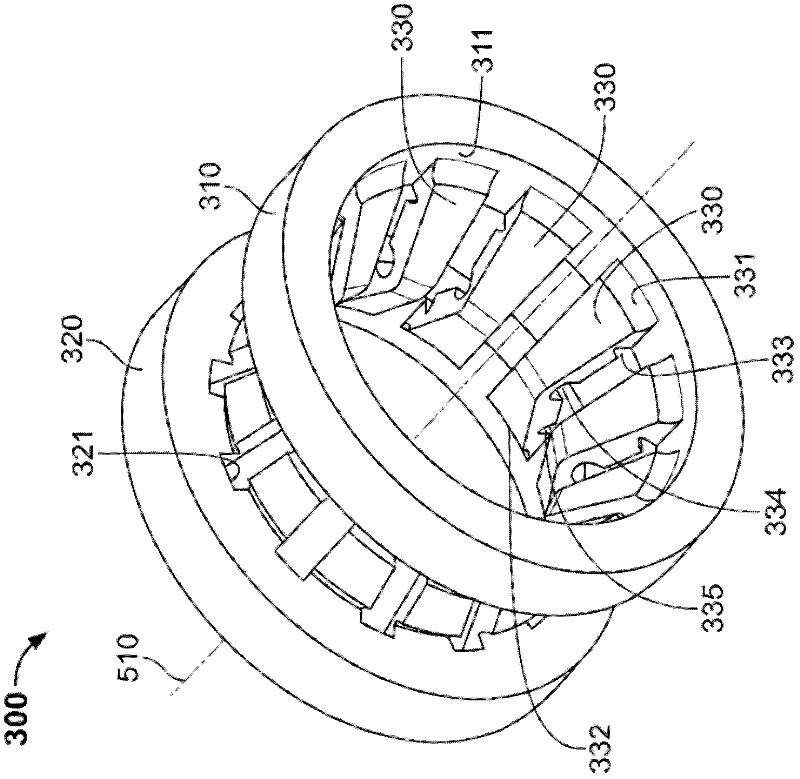
[0023] The cable gland 10 includes a nut 100 , a clamping ring 300 and a seal 400 . The nut 100, the clamping ring 300, the seal 400 and the counter part 200 are each substantially rotationally symmetrical, and in figure 1 They are tangent to a plane extending through a common longitudinal axis 510 which forms the axis of symmetry.

[0024] The nut 100 has a guide portion 110 and a threaded portion 120 . The first feed-through hole 130 extends along the longitudinal axis 510 thr...


PUM


Abstract

A clamping ring for a cable gland has a first ring and a second ring, the first ring and the second ring being orientated coaxially relative to a common longitudinal axis. The first ring and the second ring are connected via a plurality of deformable ribs. The ribs are designed to deform in the direction of the longitudinal axis when the first ring and the second ring are brought into convergence one with the other.

Description

technical field [0001] The invention relates to a clamping ring for a cable gland, a cable gland and a method of installing a cable gland. Background technique [0002] Cable glands are known in the prior art for securing an electrically conductive cable to an electrical plug connector or cable bushing to prevent any improper separation of the cable from the plug connector or cable bushing. Cable glands are also known for simultaneously sealing the area between the cable and the plug connector or the cable bushing. [0003] Conventional cable glands are typically screwed onto the plug connector or cable bushing far enough to generate a defined torque. This has the disadvantage that any inspections undertaken for proper installation will be laborious and require specialized tools. Furthermore, it has been proven that an indeterminate loosening torque develops after a certain storage period. In some cases, this can cause the cable gland to come loose. Contents of the inve...

Claims


Application Information

Patent Timeline
IPC IPC(8): H02G15/04
CPCH01R4/646H01R13/59H01R13/5205H02G15/04H02G3/0658Y10T29/49879H01R4/48
Inventor M.斯特里洛A.里昂哈德
Owner TE CONNECTIVITY GERMANY GMBH
Why Eureka
Try Eureka