Multiple nozzle junction of textile machine, textile machine, and method for operating textile machine

A textile machine and multi-nozzle technology, which is applied in the direction of textiles and papermaking, spinning machines, continuous winding spinning machines, etc., can solve the problems of expensive and time-consuming refitting, and achieve the effect of simple refitting

Inactive Publication Date: 2020-04-10
MASCHINENFABRIK RIETER AG
View PDF22 Cites 0 Cited by
  • Summary
  • Abstract
  • Description
  • Claims
  • Application Information

AI Technical Summary

Problems solved by technology

[0010] However, this embodiment has the disadvantage that the conversion of the textile machine from

Method used


Image

  • Multiple nozzle junction of textile machine, textile machine, and method for operating textile machine
  • Multiple nozzle junction of textile machine, textile machine, and method for operating textile machine
  • Multiple nozzle junction of textile machine, textile machine, and method for operating textile machine

Examples


Embodiment Construction

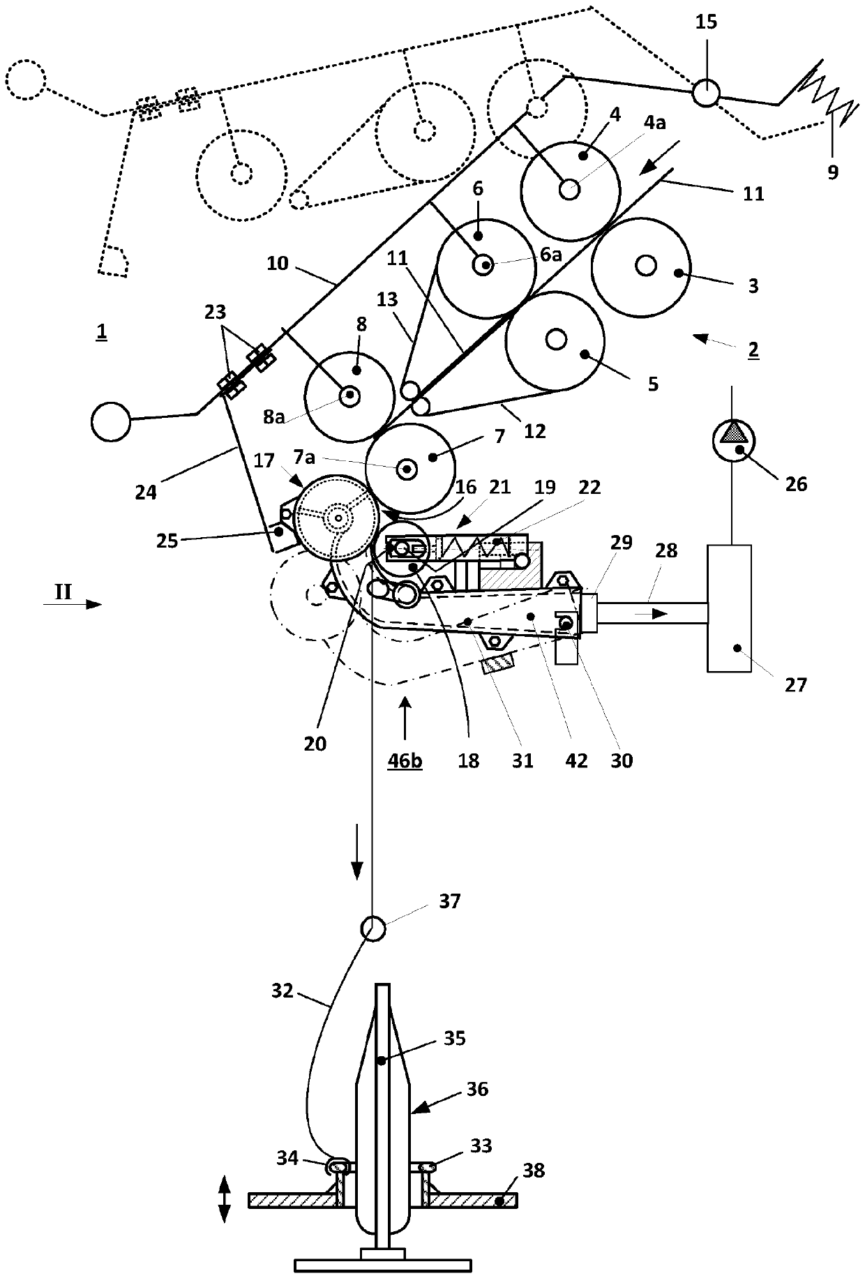
[0036] figure 1Shows a schematic side view of a spinning station 1 of a spinning machine (ring spinning machine) with a drafting mechanism unit 2 provided with a pair of input rollers 3, 4, a pair of intermediate rollers 5, 6 and output roller pair 7,8. Belts 12 , 13 are each guided around intermediate rollers 5 , 6 and are each held in their shown position around cages (not shown in detail). The upper rollers 4 , 6 , 8 of the roller pairs mentioned are designed as pressure rollers, which are mounted rotatably via axes 4 a , 6 a , 8 a on pivotably mounted pressure arms 10 . Two adjacent drafting units 2 (double drafting units) are assigned to one pressing arm 10 . The pressure arm 10 is mounted so as to be pivotable about an axis 15 and is loaded, as schematically shown, by a spring element 9 . The spring element can also be an air hose, for example. The rollers 4 , 6 , 8 are pressed against the lower rollers 3 , 5 and 7 of the roller pair by the schematically indicated sp...


PUM


Abstract

The invention relates to a multiple nozzle junction (29) of a textile machine, particularly of a ring spinning frame, for the alternative connection of a compression device (46b) or a suction pipe device (46b) to a suction line of the textile machine. The invention also relates to a textile machine equipped with a multiple nozzle junction (29).

Description

technical field [0001] The invention relates to a multi-nozzle connection for a suction line of a textile machine according to the independent claims and to a textile machine equipped with the multi-nozzle connection. Background technique [0002] Various embodiments are known from practice in which a compression device is arranged after the compression (compression) of the fiber material (sliver) output by the drafting unit. Following such a compression device, the compressed fiber material is fed to the eddy current generating device after passing the clamping point. Such a vortex generating device consists, for example, in a ring spinning machine of a rotor which runs around a ring, wherein the yarn produced is wound onto a rotating sleeve. As the compression device, a suctioned circumferential perforated suction roller or a circumferential belt provided with perforations is mainly used. In this case, using corresponding inserts, a specific suction area is defined on th...

Claims


Application Information

Patent Timeline
IPC IPC(8): D01H1/14D01H5/26D01H5/66D01H1/02
CPCD01H1/025D01H1/14D01H5/68D01H5/66D01H5/72
Inventor H.卡佩勒M.法纳
Owner MASCHINENFABRIK RIETER AG
Why Eureka
Try Eureka