Gas supply for a gas burner

A gas burner and gas technology, which is applied in the field of nozzle discharge, can solve the problems of non-releasing nozzles, no longer replaceable, etc.

Active Publication Date: 2010-11-17
BSH BOSCH & SIEMENS HAUSGERAETE GMBH
View PDF5 Cites 0 Cited by
  • Summary
  • Abstract
  • Description
  • Claims
  • Application Information

AI Technical Summary

Problems solved by technology

This possibility of producing a gas-tight connection between the gas connection pipe and the nozzle requires a high technical precision and exposes the disadvantage that it involves a non-releasable connection and the nozzle is no longer replaceable

Method used


Image

  • Gas supply for a gas burner
  • Gas supply for a gas burner
  • Gas supply for a gas burner

Examples


Embodiment Construction

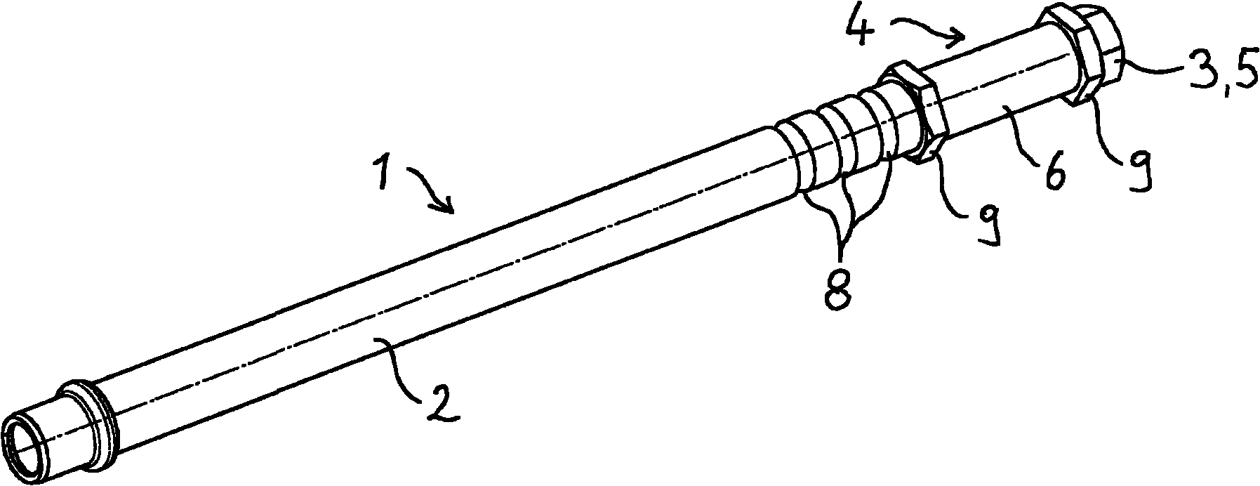
[0032] figure 1 A perspective view of a component 1 according to the invention with a straight nozzle holder 4 into which the nozzle 3 is screwed is shown in detail. The nozzle 3 has a hexagonal outer contour 5 on which a screwdriver can be placed. In order to hold the nozzle holder 4 during the screw-in process, at least one further hexagonal outer contour 9 is provided on the nozzle holder 4 . Reference numeral 8 designates grooves produced by crimping which surround the gas connection pipe 2 . The nozzle holder 4 is connected in a gas-tight manner to the gas connection pipe 2 by deformation (not visible in the figure) caused by crimping inside the gas connection pipe 2 . The area marked with the reference numeral 6 is the fastening section 6 which is used for fastening the component 1 on the gas burner.

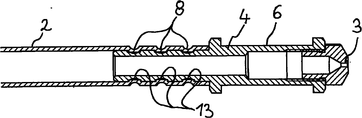
[0033] figure 2 shows that by following the present invention figure 1 The axial section of the component 1 in the region of the nozzle holder 4 , where one can see ...


PUM


Abstract

The invention relates to a component (1) for supplying gas to the gas burner of gas range or gas oven, which has a gas connecting tube (2) that is connected at a gas entrance with a gas valve and in a gastight connection with a nozzle (3) at a gas exit. The nozzle is a part of a nozzle injector unit. A nozzle holder (4) is at least partly arranged inside the gas connecting tube (2), and is in gastight connection with the gas connecting tube by deforming the gas connecting tube (2), and the nozzle holder (4) includes a thread at a gas output side end, and the nozzle (3) is fixed over a gastight screw connection at the nozzle holder (4) by the thread.

Description

technical field [0001] The invention relates to a component for supplying fuel gas to a gas burner of a gas stove or a gas oven, which has a gas connection pipe connected to a gas source at its gas inlet and connected to a gas The outlet has a gas-tight connection to a nozzle from which fuel gas is discharged, and a method for producing such a component. Background technique [0002] In order to connect the gas connection pipe to the nozzle, it is known that the gas connection pipe is provided with a thread. Pre-cut or self-cut threads can be used here when the nozzle is screwed in. Depending on the material of the gas connecting pipe, the two possibilities offer different degrees of processing difficulty. The direct screwing of the nozzle into the gas connection is shown, for example, in document US Pat. No. 5,735,685. [0003] Furthermore, it is known to press the nozzle directly onto the gas connection. This possibility of producing a gas-tight connection between gas ...

Claims


Application Information

Patent Timeline
Patent Type & Authority Applications(China)
IPC IPC(8): F23D14/46F23D14/48
CPCF24C3/08F16L13/141F16L15/006F23D14/065F23D14/46F23D14/64F23K2400/20F24C3/008
Inventor C·卡多J·诺曼
Owner BSH BOSCH & SIEMENS HAUSGERAETE GMBH
Why Eureka
Try Eureka