Rotor

一种转子、基体的技术,应用在制造电动马达的转子领域,能够解决昂贵工艺、困难等问题,达到成本低廉、小负担、延长寿命的效果

Active Publication Date: 2012-12-19
VTESCO TECH GMBH
View PDF7 Cites 4 Cited by
  • Summary
  • Abstract
  • Description
  • Claims
  • Application Information

AI Technical Summary

Problems solved by technology

However, this is a very difficult and therefore expensive process, and moreover, this method often leads to unsatisfactory results

Method used


Image

  • Rotor
  • Rotor
  • Rotor

Examples


Embodiment Construction

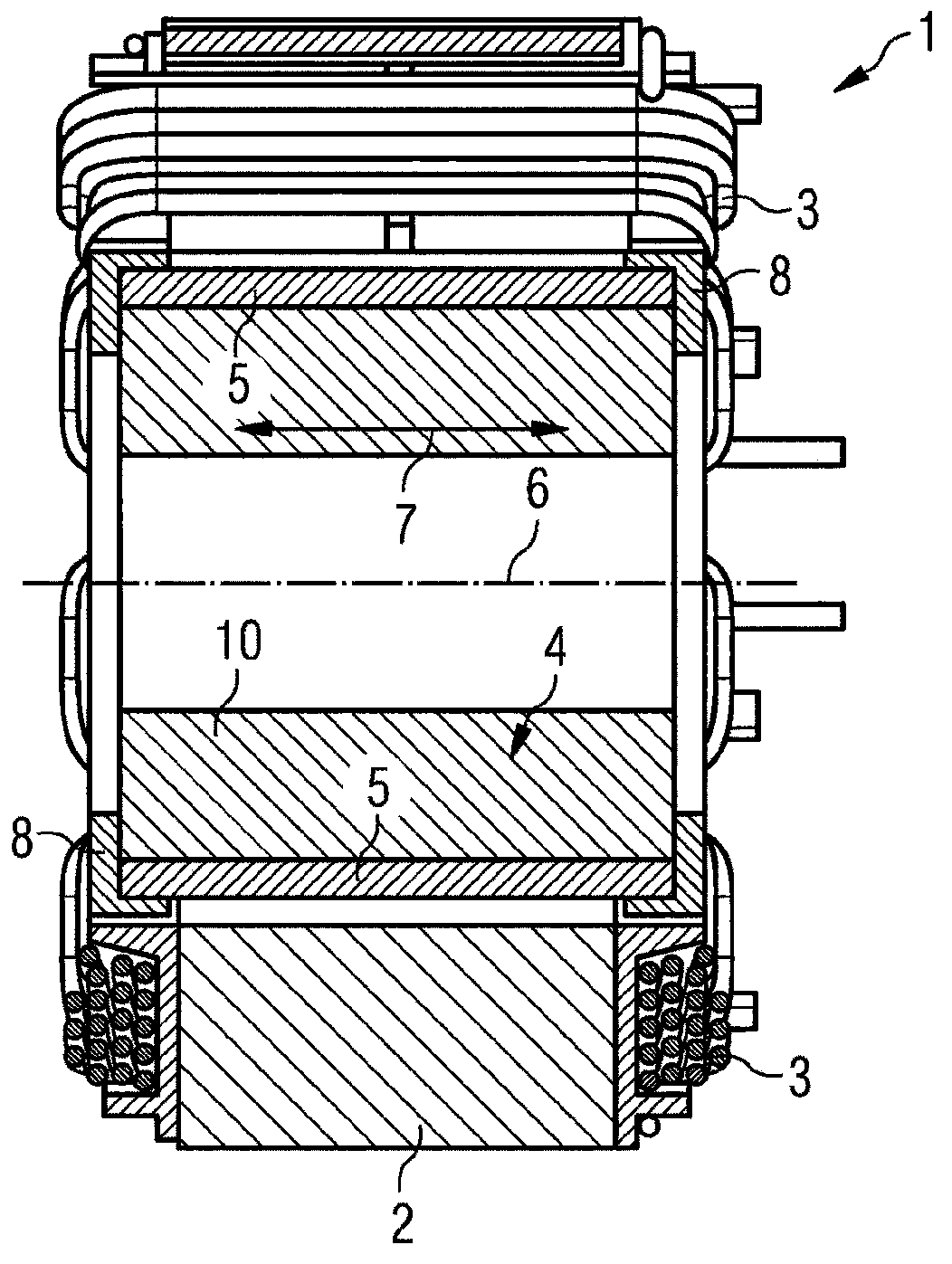
[0021] figure 1 An electric motor 1 with a stator 2 and a rotor 4 is shown. This can be, for example, a so-called reluctance motor. Arranged on the stator 2 are coils 3 which can be passed through with a rectified current, whereby an exchange magnetic field can be generated. The rotor 4 is mounted rotatably on a shaft 6 and has a base body 10 and permanent magnet elements 5 . The permanent magnet element 5 is held on the base body 10 by the connecting sleeve 9 and the locking element 8 . The arrow indicates the axial direction 7 in which, for example, the connecting sleeve 9 can be pushed over the base body 10 . The permanent magnet element 5 is designed here as a square, which is a particularly cost-effective design. However, it can also be embodied in the form of a housing.

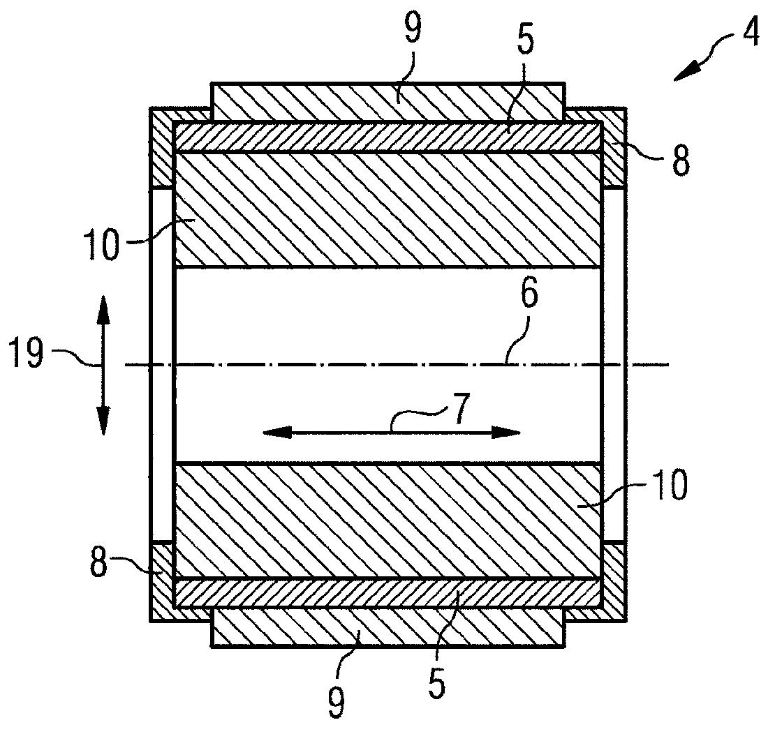
[0022] exist figure 2 The construction of the rotor 4 is shown in more detail in . It can be seen that there are a number of permanent magnet elements 5 which are arranged on the cylindrical out...


PUM


Abstract

The invention relates to a rotor for an electric motor, wherein the rotor comprises a main body on which at least one support surface is formed, to which at least one permanent magnet element is attached. In order to provide a rotor for an electric motor in which the at least one permanent magnet element is cost-effectively fastened to the main body in a precisely predetermined position, the main body (10) is partially surrounded by a joining sleeve (9) having chamber walls (15), wherein the chamber walls (15), together with the support surfaces (13), form at least one chamber (17) in which the at least one permanent magnet element (5) is arranged, wherein the joining sleeve (9) fixes the position of the permanent magnet element (5) in the radial direction (19) on the main body (10) and a locking element (8) is molded onto the main body (10), said locking element closing the chamber (17); and thereby fixing the position of the permanent magnet element (5) in the axial direction (7) on the main body (10).

Description

technical field [0001] The invention relates to a rotor for an electric motor, wherein the rotor has a base body on which at least one bearing surface is formed, the bearing surface having at least one permanent magnet element. Furthermore, the invention relates to a method for producing a rotor of an electric motor. Background technique [0002] Many rotors for electric motors of the type mentioned at the outset are known and their applications are varied. There are different methods for fastening the permanent magnet elements to the base body of the rotor. It is known, for example, from DE 10 2005 052 870 A1 to completely injection-mould the permanent magnet elements with plastic and thus fix them to the base body. In this case, however, it is difficult to keep the permanent magnet elements exactly in their position during the injection molding process. Since the injection molding material is injected at extremely high pressures during the injection molding process, the...

Claims


Application Information

Patent Timeline
Patent Type & Authority Applications(China)
IPC IPC(8): H02K15/03H02K1/27
CPCH02K15/03H02K1/278H02K1/28H02K1/02
Inventor 吕迪格·布兰道库尔特·西巴尔德
Owner VTESCO TECH GMBH
Why Eureka
Try Eureka