

Motor switch with automatic identification
An automatic identification and switching technology, which is applied in the direction of electrical components, emergency protection circuit devices, etc., can solve problems such as high cost, unsuitable for popularization and application, and complicated circuits
- Summary
- Abstract
- Description
- Claims
- Application Information
AI Technical Summary
Problems solved by technology
Method used
Image

Examples
Embodiment 1
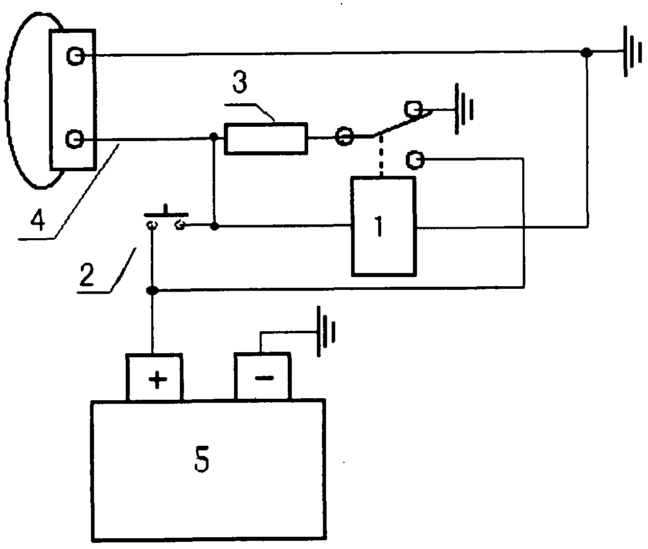
[0030] Such as figure 1 As shown, a motor switch for automatic identification includes a relay (1) providing motor power, characterized in that: the self-recovery fuse thermal fuse in which the control terminal of the relay (1) providing motor power is connected in series with the common terminal of the relay (1) is used. The sensitive resistor (3) is electrically connected to measure the stalling of the motor. According to the large resistance generated by the self-recovery fuse thermistor (3) after the motor is blocked, the work of the control terminal of the relay (1) is stopped, and the working power of the motor is turned off.
[0031] A resettable fuse thermistor (3) is connected in series with the common terminal of the relay (1) to be electrically connected to the motor positive input terminal (4), and the positive electrode of the control terminal of the relay (1) is electrically connected to the motor positive terminal of the resettable fuse thermistor (3). Electric ...
Embodiment 2
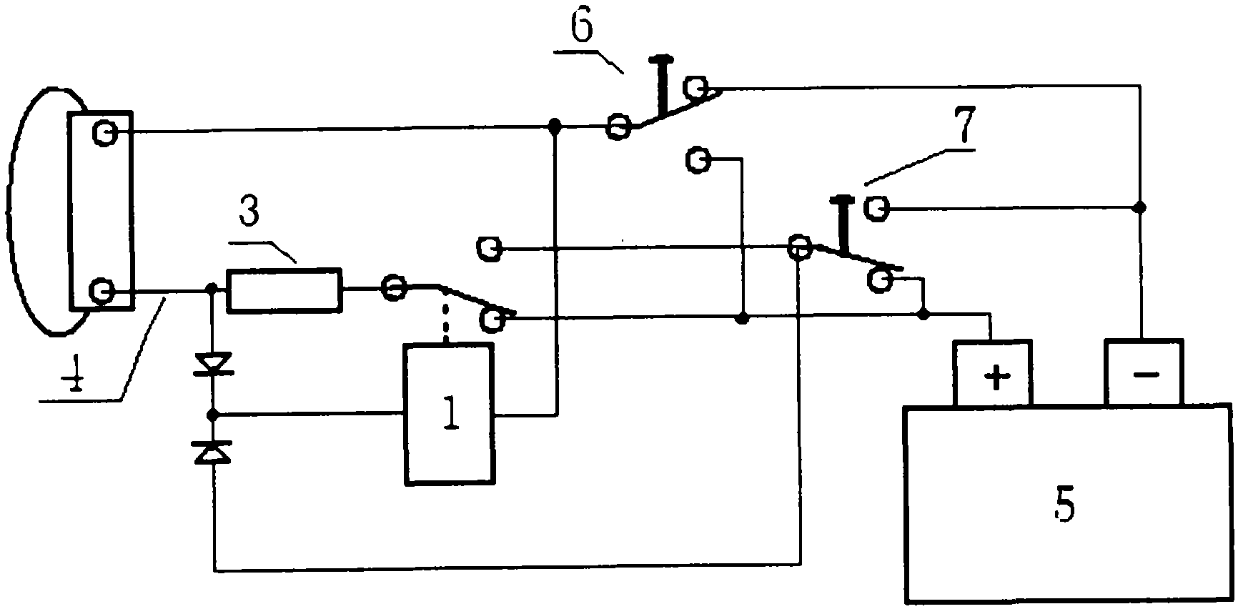
[0036] This embodiment is an embodiment in which the manual window closing button switch (7) operates as a power trigger switch
[0037] Such as figure 1 As shown, a motor switch for automatic identification includes a relay (1) providing motor power, characterized in that: the self-recovery fuse thermal fuse in which the control terminal of the relay (1) providing motor power is connected in series with the common terminal of the relay (1) is used. The sensitive resistor (3) is electrically connected to measure the stalling of the motor. According to the large resistance generated by the self-recovery fuse thermistor (3) after the motor is blocked, the work of the control terminal of the relay (1) is stopped, and the working power of the motor is turned off.
[0038] A resettable fuse thermistor (3) is connected in series with the common terminal of the relay (1) to be electrically connected to the motor positive input terminal (4), and the positive electrode of the control t...
Embodiment 3
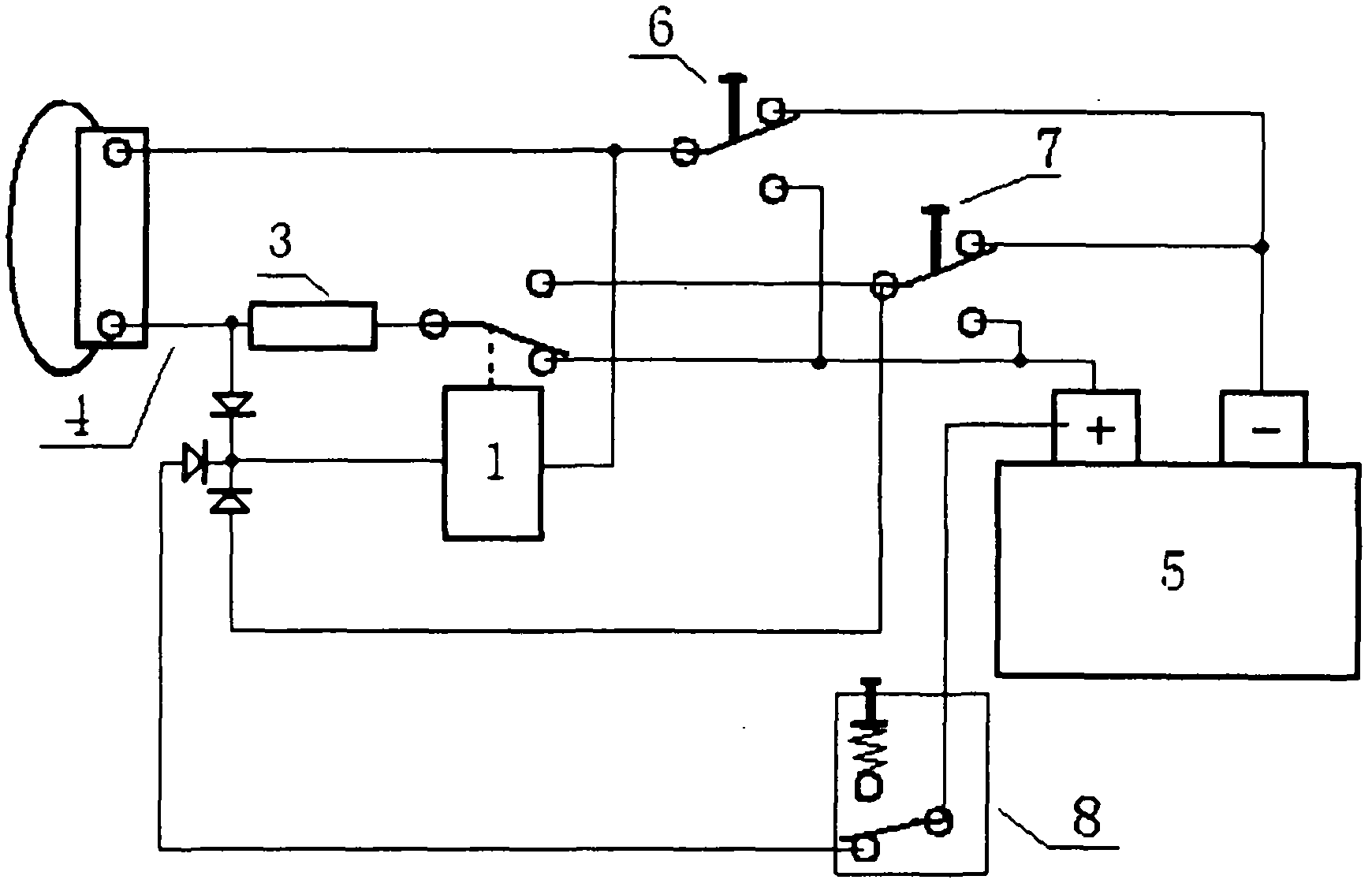
[0045] This embodiment is an embodiment in which the central control door lock of the car is closed by the positive electric trigger and operates as a power trigger switch
[0046] Such as figure 1 As shown, a motor switch for automatic identification includes a relay (1) providing motor power, characterized in that: the self-recovery fuse thermal fuse in which the control terminal of the relay (1) providing motor power is connected in series with the common terminal of the relay (1) is used. The sensitive resistor (3) is electrically connected to measure the stalling of the motor. According to the large resistance generated by the self-recovery fuse thermistor (3) after the motor is blocked, the work of the control terminal of the relay (1) is stopped, and the working power of the motor is turned off.
[0047] A resettable fuse thermistor (3) is connected in series with the common terminal of the relay (1) to be electrically connected to the motor positive input terminal (4),...
PUM
 Abstract
Description
Claims
Application Information