
Method and device for monitoring working status of different system devices

A technology of working status and system equipment, applied in the direction of transmission system, digital transmission system, electrical components, etc., can solve the problems that cannot meet the requirements of the monitoring system, fail to meet the monitoring, and low work efficiency, so as to reduce the mean maintenance time of failure , Reduce the link of manual intervention, improve the effect of reliability and maintainability

Inactive Publication Date: 2012-07-04
GUANGDONG XUNTONG TECH
View PDF4 Cites 9 Cited by
  • Summary
  • Abstract
  • Description
  • Claims
  • Application Information

AI Technical Summary

Problems solved by technology

[0002] With the continuous progress and development of monitoring technology, the scope of monitoring is getting larger and larger, and there are more and more devices in the monitoring system. Once a device fails and cannot be found in time, it will become a dead corner of monitoring and cannot achieve monitoring. the goal of
When the monitoring system equipment fails, the corresponding management personnel will manually locate and troubleshoot the fault, and its work efficiency is relatively low
[0003] With the continuous expansion of monitoring services, the requirements for the reliability and manageability of monitoring equipment are getting higher and higher, and the method of manual intervention after the event can no longer meet the requirements of the current monitoring system.

Method used

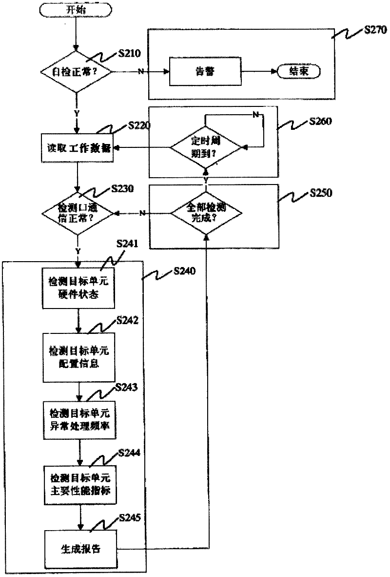
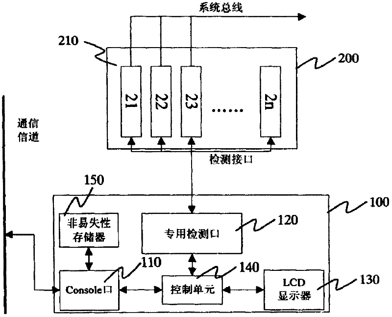

Image

  • Method and device for monitoring working status of different system devices
  • Method and device for monitoring working status of different system devices
  • Method and device for monitoring working status of different system devices

Examples


Embodiment 1

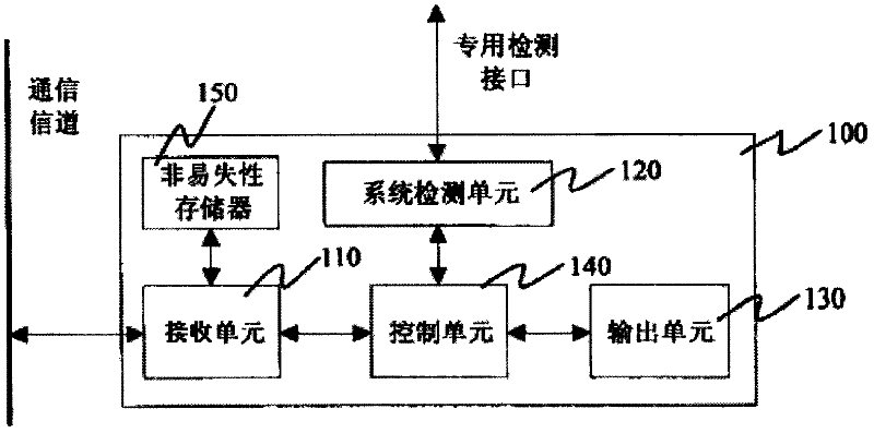
[0038] The system failure detection device 100 of the present invention is mainly composed of four functional units, including a receiving unit 110 , a detection unit 120 , an output unit 130 and a control unit 140 .

[0039] Such as figure 1 As shown, the detection device 100 can be divided into four functional units inside, and the functional units are connected together through an internal bus to form a complete system. The receiving unit 110 receives user configuration information from the man-machine interface, and stores it in the non-volatile memory 150 inside the detection device. The non-volatile memory 150 can be EEPROM (Electrically Erasable Programmable Read-Only Memory, electrically erasable programmable Read memory), FALSH memory or micro hard disk, etc., the configuration information can reach the control unit 140 through the internal bus interface, and the control unit 140 sends the information obtained from the receiving unit 110 to the detection unit 120, and...


PUM


Abstract

The invention belongs to the technical field of data monitoring, particularly discloses a method and a device for monitoring working status of different system devices. The device comprises a receiving unit, a control unit, a detection unit and an output unit. The receiving unit is used for receiving user configuration information through a communication channel and transmitting the configuration information to the control unit. The control unit is connected with the receiving unit and used for sending the configuration information to the detection unit and receiving detection results fed back by the detection unit. The detection unit is connected with the control unit and connected with a monitored system through a detection interface and is used for detecting hardware status, configuration information, functional index and / or performance index of the monitored system according to the configuration information to generate detection results which are fed back to the control unit. The output unit is connected with the control unit and used for outputting the detection results sent by the control unit. A method for the device to perform system fault automatic detection is provided.

Description

technical field [0001] The invention belongs to the technical field of data monitoring, and in particular relates to a method and a device for monitoring the working states of different system equipment. Background technique [0002] With the continuous progress and development of monitoring technology, the scope of monitoring is getting larger and larger, and there are more and more devices in the monitoring system. Once a device fails and cannot be found in time, it will become a dead corner of monitoring and fail to achieve monitoring. the goal of. When the monitoring system equipment fails, the corresponding management personnel will carry out manual fault location and troubleshooting, and its work efficiency is relatively low. [0003] With the continuous expansion of the monitoring business, the requirements for the reliability and manageability of the monitoring equipment are getting higher and higher, and the manual intervention after the event can no longer meet th...

Claims


Application Information

Patent Timeline
IPC IPC(8): H04L12/24H04L12/26
Inventor 陈色桃
Owner GUANGDONG XUNTONG TECH
Learn More