
Plug receptacle

A technology of plug socket and plug, which is applied in the direction of two-part connection device, electrical component, device for preventing wrong connection, etc., can solve the problem of increasing the size of plug receiving part 302, socket unit 300, etc., to prevent reverse insertion and prevent proportional Increased, easy-to-position effect

Inactive Publication Date: 2012-07-04
PANASONIC CORP
View PDF6 Cites 3 Cited by
  • Summary
  • Abstract
  • Description
  • Claims
  • Application Information

AI Technical Summary

Problems solved by technology

However, causing an increase in the size of the plug receiving portion 302 leads to a problem in that the size of the outlet unit 300 increases.

Method used


Image

  • Plug receptacle
  • Plug receptacle
  • Plug receptacle

Examples


no. 1 example

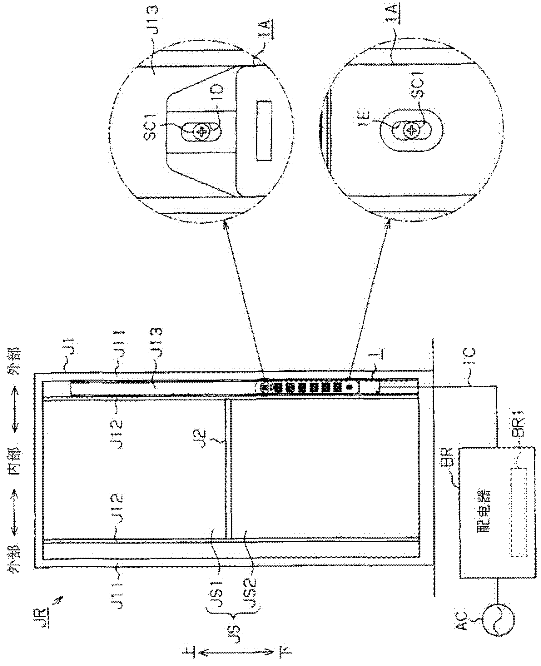
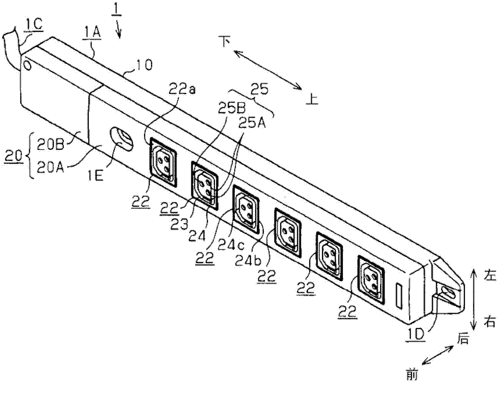
[0055] will refer to Figure 1 to Figure 11 A plug socket according to a first embodiment of the present invention, which is implemented as a socket attached to an information rack for accommodating a server device or the like, will be described.

[0056] First, see the figure 1 The relationship between the information rack JR and the plug socket 1 and the power supply structure of the plug socket 1 will be described. In Figure 3 to Figure 11 In FIG. 2 , the cable 1C of the plug base 1 is omitted, and the plug 2 is omitted in FIG. 2 .

[0057] Such as figure 1 As shown in , the information rack JR is formed in a box shape by the frame body J1 forming its outer frame. The information rack JR includes a housing section JS that has an open front portion and serves as a space for housing a server device (not shown). In addition, the information shelf JR includes a dividing member J2 for dividing the storage section JS into an upper storage section JS1 and a lower storage s...

no. 2 example

[0154] will refer to Figure 12 to Figure 15 A second embodiment will be described in which the plug socket of the present invention is implemented as a table tap connected to a DC outlet buried in a wall of a building. Figure 15 Descriptions of cables and plugs are omitted.

[0155] will refer to Figure 12 The entire DC power distribution system 70 installed at the house H will be described.

[0156] Such as Figure 12 As shown in , a house H is provided with a DC power supply unit 71 for outputting DC power; and an electric device 72 that operates with DC power. DC power is supplied to the electric device 72 via a DC power supply line Wdc connected to an output terminal of the DC power supply unit 71 .

[0157] Furthermore, a DC breaker 73 is provided between the DC power supply unit 71 and the electric device 72 . The DC breaker 73 monitors the current flowing in the DC power supply line Wdc, and limits or interrupts the supply of DC power from the DC power supply un...


PUM


Abstract

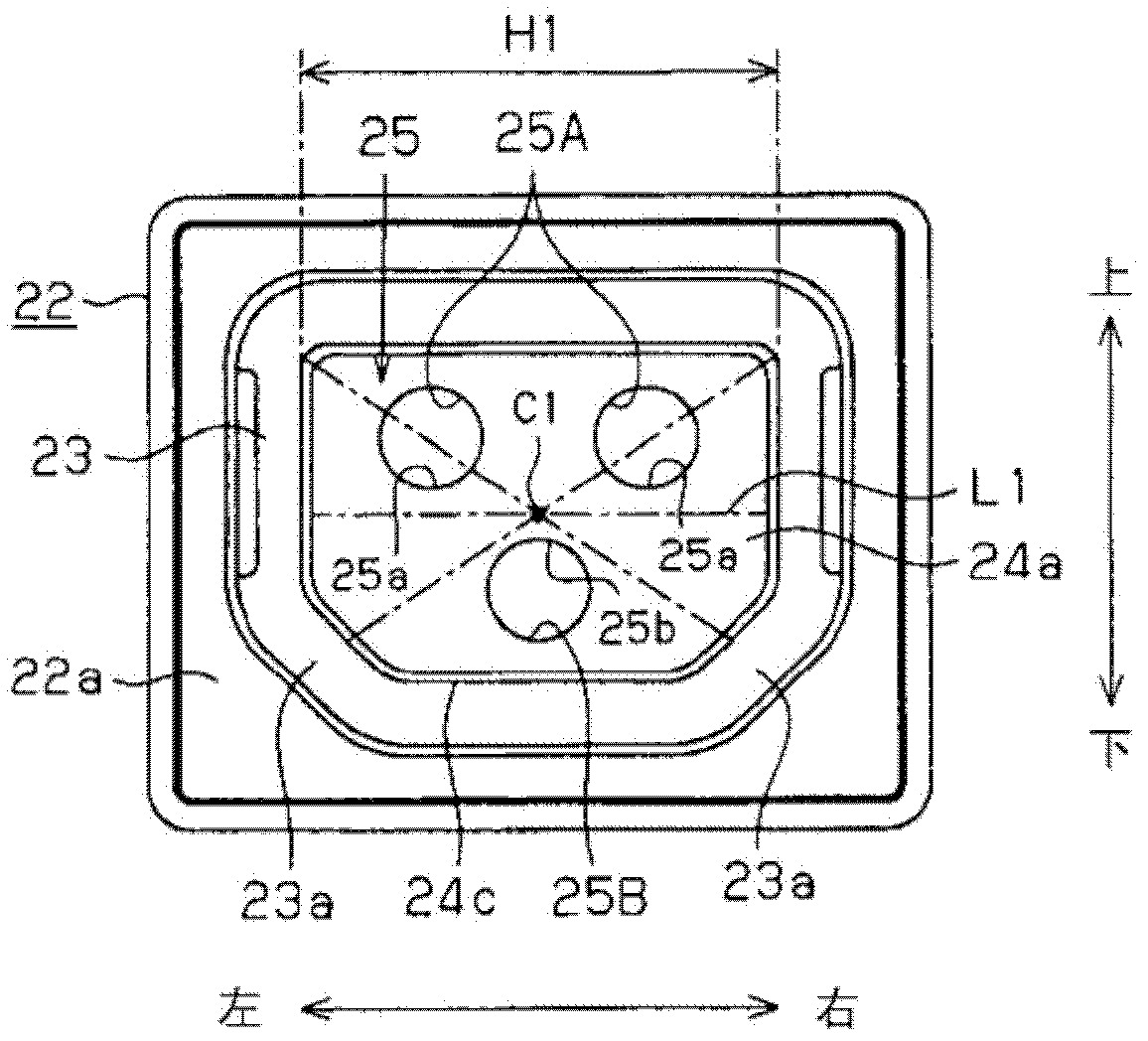
A plug receptacle includes a housing having at least one outlet unit to which a plug is adapted to be connected to supply a DC power to the plug, and a cable, connected to the housing, for supplying the DC power to the housing. The outlet unit includes a plug- receiving portion having a plurality of substantially circular pin- inserting holes into which plug pins of the plug are inserted and an insertion groove formed to surround a periphery of the plug-receiving portion. The plug- receiving portion has a substantially quadrangular shape viewed from a front side thereof. The insertion groove is adapted to receive a surrounding wall of the plug and has a substantially quadrangular shape viewed from the front side. The pin-receiving holes are arranged along one side of the plug- receiving portion serving as a reference side and offset closer to the reference side than an opposite side to the reference side.

Description

technical field [0001] The present invention relates to a socket to which a plug is adapted to be connected, and which comprises: a housing having a socket unit for supplying DC power to the plug; and a cable connected to the socket. described shell. Background technique [0002] Conventionally, there is known a plug socket having a socket unit to which a plug of an electric device (such as a personal computer or a telephone) is detachably connected, and which is used to , a table tap) to supply operating power (AC power) to an electric device (for example, see Japanese Patent Application Publication No. H07-211384 (JP07-211384A)). [0003] Meanwhile, most electric devices utilize direct current (DC) power as their driving power. To this end, alternating current (AC) power supplied from an alternating current (AC) outlet is converted into DC power with an AC-DC converter and then fed to electric devices. Power loss occurs when the AC-DC converter converts AC power to DC p...

Claims


Application Information

Patent Timeline
Patent Type & Authority Applications(China)
IPC IPC(8): H01R13/64
CPCH01R13/64H01R2103/00H01R25/003H01R24/76
Inventor 别所敬介东出浩二川本隆司滝井利之
Owner PANASONIC CORP
Learn More