Automatic fillet welding device and automatic fillet welding method

A technology of automatic welding and fillet welding, which is used in welding equipment, auxiliary devices, welding equipment, etc., can solve the problems of the terminal that cannot be detected in the welding range, and cannot be specifically designated to be detected, and achieve the effect of reliable detection.

Active Publication Date: 2012-07-11
JAPAN MARINE UNITED CORP
View PDF8 Cites 5 Cited by
  • Summary
  • Abstract
  • Description
  • Claims
  • Application Information

AI Technical Summary

Problems solved by technology

[0006] In the prior art described above, in the technology of detecting the vertical plate existing on the travel route of the trolley, when there is no such vertical plate, the end of the welding range cannot be detected.
In addition, in the technology of detecting the start and end of the opening of the welded vertical plate, when the start of the opening has been detected, it is not possible to specify which one to detect until the end of the opening is detected. The beginning of the opening or the end of the riser
Therefore, the above-mentioned prior art cannot also bring into play the desired effect outside the limited situation

Method used


Image

  • Automatic fillet welding device and automatic fillet welding method
  • Automatic fillet welding device and automatic fillet welding method
  • Automatic fillet welding device and automatic fillet welding method

Examples


Embodiment Construction

[0045] Embodiments of the present invention will be described below with reference to the drawings.

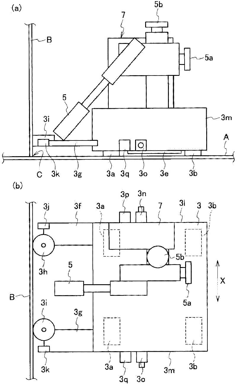
[0046] figure 1 The schematic structure of the fillet automatic welding apparatus in one Embodiment of this invention is shown, (a) is a side view, (b) is a top view.

[0047] Such as figure 1 As shown in (a), an automatic fillet weld welding device 1 (hereinafter simply referred to as a welding device) in this embodiment includes a trolley 3 and a welding torch 5 . The trolley 3 is configured to have two travel wheels 3a, 3b in the front and rear respectively, and utilizes a motor 3c (refer to figure 2 ) dynamics can be as figure 1 The travel direction X shown in (b) reciprocates. In addition, the four traveling wheels 3a, 3b may be independently driven by respective motors.

[0048] Such as figure 1 As shown in (a), a permanent magnet 3e is arranged on the bottom surface of the trolley 3, and the permanent magnet 3e is attached to the plate A (corresponding to the joi...


PUM


Abstract

The present invention relates to an automatic fillet welding device, which can reliably detect the tip end and the tail end of the fillet welding range in any environment, wherein in a welding apparatus (1) with a trolley (3) traveling on a plate material (A), at the periphery of guide rollers (3h, 3i) rotating on a plate material (B) fillet-welded on the plate material (A), there are provided proximity sensors (3j, 3k).additionally, the side surfaces (31, 3m) of the trolley are respectively provided with proximity sensors (3p, 3q) for detecting the plate material (A) on which the trolley travels. Each proximity sensor uses an eddy current sensor for detecting a plate material of magnetic mechanism. When any one of the proximity sensors (3p, 3q) do not detect the plate material (A), or any one of the proximity sensors (3j, 3k) do not detect the plate material (B), the welding of a welding gun is stopped. But, when the proximity sensors (3p, 3q) are all in the period of detecting the plate material (A), the trolley continuously travels.

Description

technical field [0001] The present invention relates to a fillet weld automatic welding device and a fillet weld automatic welding method for automatically welding a fillet weld with a welding torch mounted on an automatically traveling trolley Background technique [0002] As an automatic welding device that performs automatic welding using a welding torch mounted on a self-propelled trolley, a technique for detecting the start and end of a welding range is known. Specifically, detect the vertical plate that exists on the traveling route of the trolley, judge that it is the end of the welding range, then stop the welding action (as Patent Document 1), and detect the beginning and end of the opening of the vertical plate to be welded, When welding is unnecessary, the welding action is interrupted (eg, Patent Document 2). [0003] Prior art literature: [0004] Patent Document 1: Japanese Patent Application Laid-Open No. 11-216566 [0005] Patent Document 2: Japanese Paten...

Claims


Application Information

Patent Timeline
Patent Type & Authority Applications(China)
IPC IPC(8): B23K9/12B23K9/32G05B19/18
CPCB23K37/0258B23K37/0264B23K37/0294G05D1/0231G05D1/0255G05D1/0259
Inventor 木治升吉川正幸草场卓哉
Owner JAPAN MARINE UNITED CORP
Why Eureka
Try Eureka