Numerical control device and method for controlling numerical control device

A technology of numerical control device and control part, which is applied in the direction of digital control, positioning device, electrical program control, etc., can solve the problem of inability to shorten the tool change cycle and so on.

Active Publication Date: 2012-07-11
BROTHER KOGYO KK
View PDF6 Cites 17 Cited by
  • Summary
  • Abstract
  • Description
  • Claims
  • Application Information

AI Technical Summary

Problems solved by technology

Therefore, the tool change cycle cannot be shortened

Method used


Image

  • Numerical control device and method for controlling numerical control device
  • Numerical control device and method for controlling numerical control device
  • Numerical control device and method for controlling numerical control device

Examples


Embodiment Construction

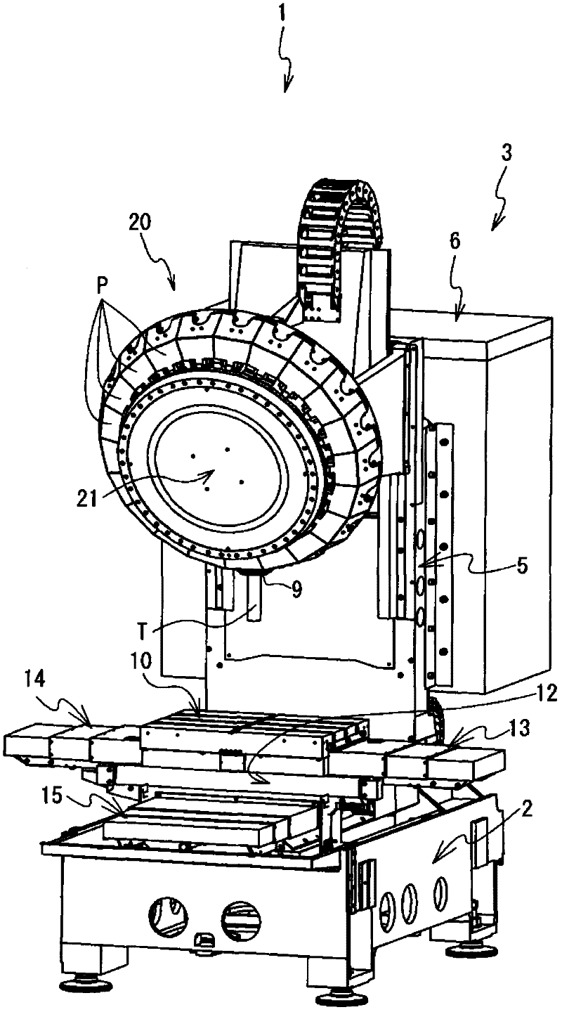
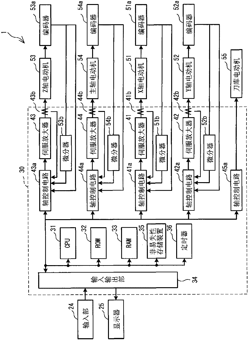
[0017] Embodiments of the present invention will be described below with reference to the drawings. figure 2 The numerical controller 30 is an embodiment of the present invention. The numerical controller 30 controls the machine tool 1 according to the processing program (refer to figure 1 ) axis movement, cutting action, tool change action, etc. The machine tool 1 cuts the workpiece by using the relative movement between the workpiece and the tool.

[0018] The structure of the machine tool 1 will be described. Such as figure 1 As shown, the machine tool 1 includes a base 2, a machine main body 3, a tool changer 20, and a protective cover (not shown). Base 2 is made of iron. The machine main body 3 is located on the upper part of the base 2 and is used for cutting the workpiece. The tool changing device 20 is located on the upper part of the machine main body 3 . The tool changing device 20 is used for changing the tool T installed on the main shaft 9 of the machine b...


PUM


Abstract

The invention relates to a numerical control device and a method for controlling the numerical control device. The CPU of the numerical control device calculates the difference between the directional time (Ts) and the rising time of the Z axis origin (Tz). When Ts is greater than Tz, the CPU fast rise along the Z axis at D at the time of t6. T6 is last from Ts to Tz from the time of t4. T4 is the start time of the oriented action on a main shaft. The Z axis rises fast feed D is reduced in speed after the time of t7. The Z-axis fast rising feed E starts at the time of t7. T7 is the time half ahead of the time T8. T8 is the finish time of the oriented action on the main shaft. The head of the main shaft can pass the Z-axis origin at a maximum speed without slowing down.

Description

technical field [0001] The invention relates to a numerical control device and a control method of the numerical control device. Background technique [0002] The numerical controller executes a spindle orientation operation in advance when an automatic tool change (automatic tool change) is to be performed. The numerical controller needs to stop the spindle at a rotational angle position where tool change can be performed. [0003] The numerical controller performs the lifting motion to the Z-axis origin and the spindle orientation motion at the same time when the tool is changed. The Z-axis origin is the mechanical origin of the Z-axis. After the spindle orientation operation is completed, the numerical control device starts to slow down the speed of the upward movement toward the Z-axis origin. Thereafter, the numerical control device starts an ascent operation to the ATC (tool change) position. The upward movement to the ATC position can only be started when the spin...

Claims


Application Information

Patent Timeline
Patent Type & Authority Applications(China)
IPC IPC(8): B23Q3/155G05B19/18
CPCB23Q3/15503
Inventor 阿久泽智规
Owner BROTHER KOGYO KK
Why Eureka
Try Eureka