Rear spoiler

A spoiler and airflow technology, applied in streamlined body, vehicle parts, road transport emission reduction, etc., can solve the problems of reduced downforce stability, increased air resistance, high fuel consumption, etc., to reduce driving resistance and improve downforce , The effect of increasing the blowing speed

Active Publication Date: 2015-01-21
HONDA ACCESS CORP
View PDF8 Cites 0 Cited by
  • Summary
  • Abstract
  • Description
  • Claims
  • Application Information

AI Technical Summary

Problems solved by technology

However, in order to reduce fuel consumption, it is necessary to reduce air resistance, and if the rear spoiler is made streamlined to cope with this, downforce that contributes to high-speed stability tends to be reduced, and stability at high-speed driving may decrease. such problem
[0006] In addition, in order to ensure the front and rear lift of the vehicle at high speed, a wing-shaped rear spoiler with a vehicle width is attached to the rear of the vehicle to ensure driving performance. However, there are problems of increased air resistance and high fuel consumption.

Method used


Image

  • Rear spoiler
  • Rear spoiler
  • Rear spoiler

Examples


Embodiment 1

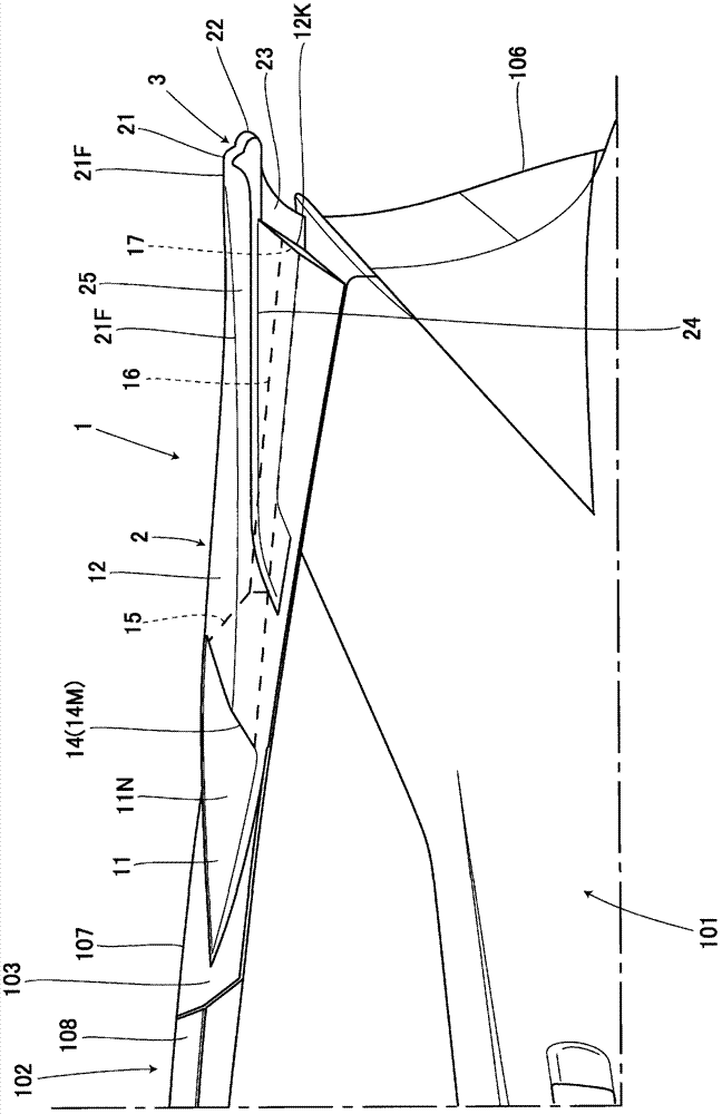
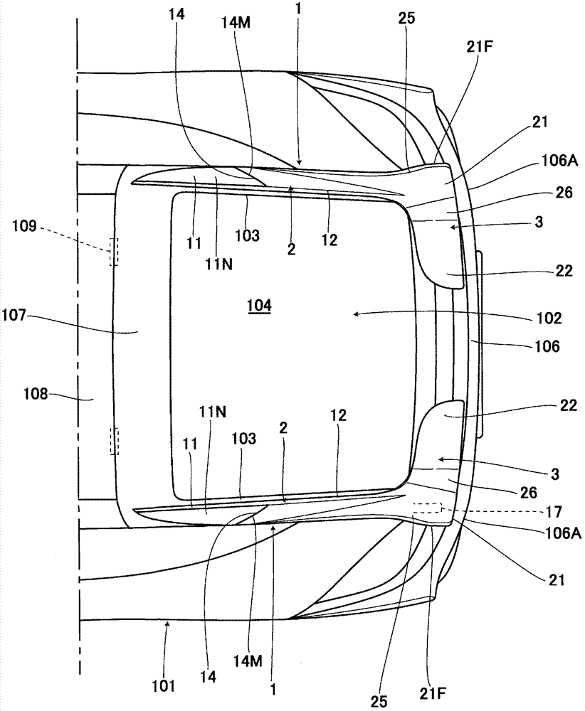
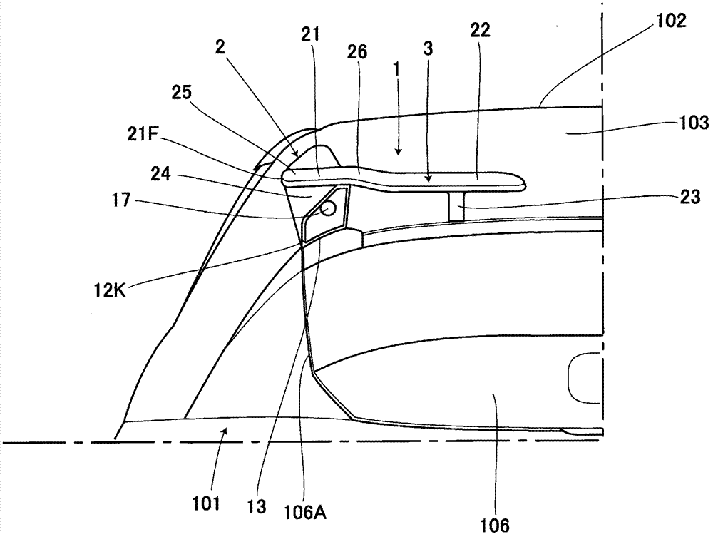
[0025] Such as Figure 1 to Figure 5 As shown, rear spoilers 1 and 1 are respectively arranged on the left and right above the rear portion of the body 101 of the self-propelled four-wheeled vehicle, and the rear spoilers 1 and 1 are independent of each other. The main body 2 having a length longer than the length in the vehicle width direction and the wing part 3 provided at the rear of the main body 2 are integrally formed. downforce. In addition, the left and right rear spoilers 1, 1 have bilaterally symmetrical shapes and are formed of synthetic resin or the like.

[0026] The rear spoiler 1 is disposed on a rear roof 102 of a vehicle body 101 , and the main body 2 is attached to a door side frame 103 that is an upper corner of the rear roof 102 . Between the left and right door side frames 103 , 103 is provided a glass 104 that slopes downward toward the vehicle rear. A substantially vertical rear surface portion 106 is provided at the rear portion of the rear roof 102...


PUM


Abstract

A rear spoiler 1 is provided which is capable of suppressing an increase in air resistance and applying a downforce to a vehicular rear portion during high-speed vehicle traveling. The rear spoiler 1 includes a main body 2 that is longer in a longitudinal direction than in a width direction. The main body 2 includes an air introduction opening 14 of air currents, and a wing 3 and an air outlet 17 communicating with the opening 14 at the rear. The air currents introduced from the opening 14 during traveling are blown off from the air outlet 17. Consequently, vortex flows generated at the rear is rectified, thus permitting travel resistance to be reduced. Further, the main body 2 is arranged in the vehicular lateral side and hence by rectifying the vortex flows generated by the air currents coming around the vehicular lateral side, the air resistance is restrained from increasing during high-speed traveling, permitting the travel resistance to be reduced.

Description

technical field [0001] The present invention relates to a rear spoiler, in particular to a rear spoiler arranged above the rear of a vehicle. Background technique [0002] Conventionally, as such a rear spoiler, it is known to install a rear spoiler on the rear upper surface of a tail gate, and to apply a down force (down force) to the rear of the vehicle body by using the rear spoiler. Thereby increasing the gripping force of the rear wheels during high-speed driving (for example, Patent Document 1), or the rear body structure of a car equipped with a spoiler (for example, Patent Document 2), etc., which has a panel, from A wing portion extending in the vehicle width direction and a leg portion supporting the wing portion are mounted on the rear upper surface of the tailgate of the rear wall panel whose rear end portion extends downward, wherein the leg portion of the rear spoiler A reinforcing portion for reinforcing the rear wall panel of the tailgate is protruded from t...

Claims


Application Information

Patent Timeline
Patent Type & Authority Patents(China)
IPC IPC(8): B62D37/02
CPCB62D35/007Y02T10/82
Inventor 福田正刚岩泽勇夫金子恭大高桥胜实
Owner HONDA ACCESS CORP
Why Eureka
Try Eureka