
Rapid ship mooring structure

A mooring and fast technology, used in mooring equipment, hulls, ship construction, etc., can solve problems such as structural inefficiency, biota cleaning, and inability to effectively relieve port pressure.

Pending Publication Date: 2022-03-08
ANHUI POLYTECHNIC UNIV MECHANICAL & ELECTRICAL COLLEGE
View PDF1 Cites 3 Cited by
  • Summary
  • Abstract
  • Description
  • Claims
  • Application Information

AI Technical Summary

Problems solved by technology

[0004] In the process of realizing the present invention, the inventors have found that at least the following problems in the prior art have not been resolved: 1. Fishing boats mooring in the port due to the low efficiency of the traditional mooring structure, port congestion will occur during the mooring peak period, and the traditional mooring system Mooring is done by manual docking and manual fixing of cables, which is time-consuming and laborious and cannot effectively relieve port pressure; 2. Fishing boats often need to go to different sea areas for fishing, which makes the boat come into contact with different organisms. Attached to the surface of its material to form a layer of bioregulatory film
The larvae and spores of the first-generation plankton landed on the bio-regulating membrane one after another, secreted mucus that enhanced adhesion, and adhered strongly through chemical bonding and electrostatic interaction, and continued to reproduce. After the death of the older generation of organisms, some of them would not automatically If it falls off, a new generation will reattach to its surface, eventually forming a large-scale biota. The biota attaches to the hull, increasing the driving resistance of the ship and increasing the driving cost of the fishing boat. Traditional mooring structures cannot clean up the biota.

Method used


Image

  • Rapid ship mooring structure
  • Rapid ship mooring structure
  • Rapid ship mooring structure

Examples


Embodiment Construction

[0038] The technical solutions in the embodiments of the present invention will be clearly and completely described below in conjunction with the accompanying drawings in the embodiments of the present invention. Apparently, the described embodiments are only some, not all, embodiments of the present invention. Based on the embodiments of the present invention, all other embodiments obtained by persons of ordinary skill in the art without making creative efforts belong to the protection scope of the present invention.

[0039] see Figure 1 to Figure 10 , the present invention provides a technical solution:

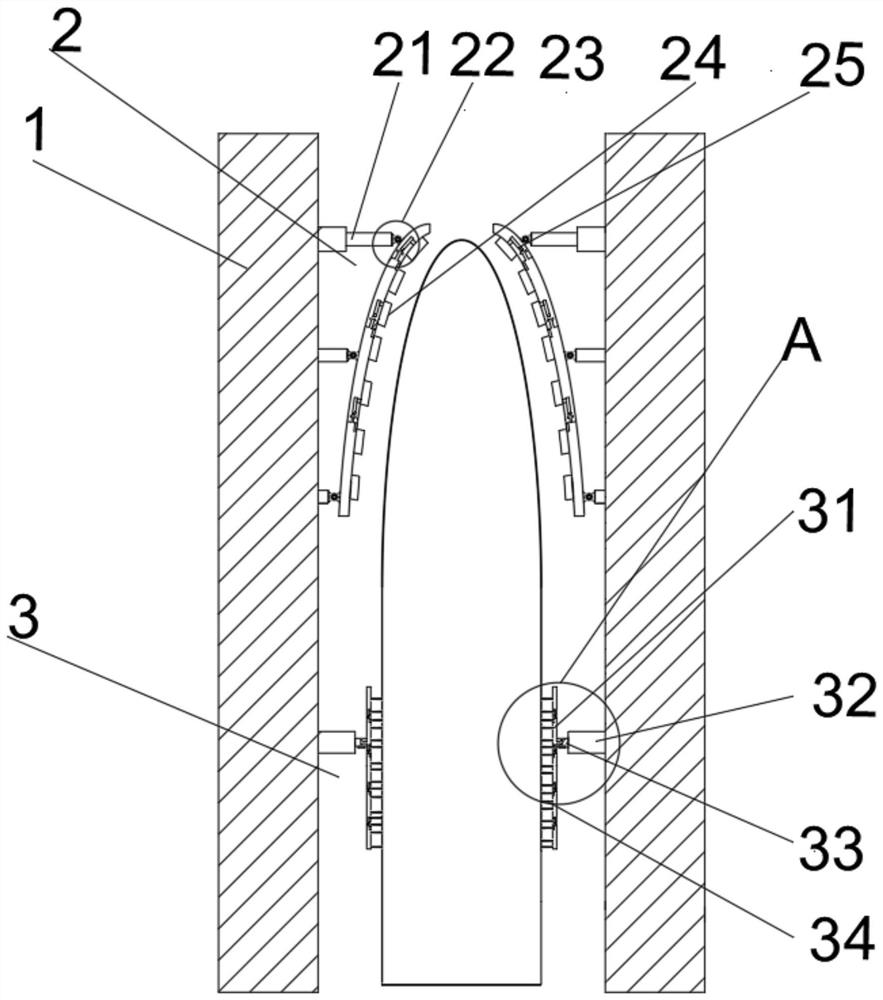
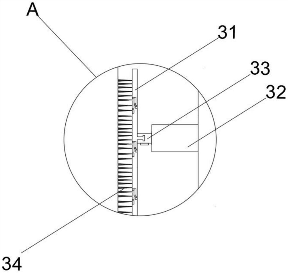
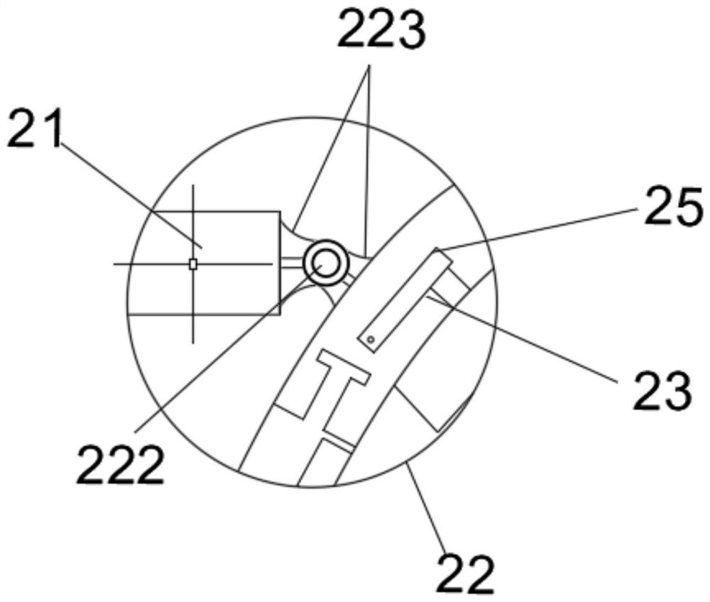
[0040] Such as Figure 1 to Figure 10 As shown, a fast mooring structure for a ship includes two groups of mooring structure supports 1, mooring structure 2, cleaning structure 3 and hull, the hull is located between two said mooring structure supports 1, and said mooring structure The mooring structure 2 and the cleaning structure 3 are arranged on the adjacent surface...


PUM


Abstract

The invention discloses a rapid ship mooring structure which comprises a set of mooring structure supports, a cleaning structure and a ship body, the ship body is located between the set of mooring structure supports, the mooring structure and the cleaning structure are arranged on the adjacent faces of the mooring structure supports, and the mooring structure is located on the upper side of the cleaning structure. According to the rapid ship mooring structure, the mooring structure and the cleaning structure are arranged, the mooring structure is used in cooperation with the multiple clamping plates through three sets of hydraulic telescopic devices, the moored ship can be rapidly berthed, the radian of the clamping plates can be adjusted to adapt to ships of different sizes, and the cleaning structure is convenient to use. Meanwhile, the ship body can be protected through buffer rubber, the ship body can be rapidly and safely berthed, the mooring speed is increased, the mooring reliability is improved, meanwhile, a cleaning plate of the cleaning structure makes contact with the ship body through a hydraulic telescopic device, a heating plate is embedded in the cleaning plate in order to remarkably improve the cleaning effect of the cleaning plate, and the heating plate and a cleaning ship brush act in a matched mode.

Description

technical field [0001] The invention relates to the technical field of fast mooring structures for ships, in particular to a fast mooring structure for small and medium-sized fishing boats. Background technique [0002] After working for a period of time, ships operating at sea need to berth at the shore. Existing ship mooring mainly utilizes the propulsion of ship power to complete the jacking of the berth post, thereby completing the berthing of the ship. However, due to the changeable sea environment, the power system of the ship will be disturbed under environmental conditions such as wind and waves, making it difficult for the ship to berth. The operation is cumbersome, and the ship is easy to be damaged due to uneven force during the berthing process, so the mooring reliability is poor and the efficiency is low. Therefore, it is necessary to design a fast mooring structure to improve the mooring efficiency of the ship . [0003] The existing patent (notification num...

Claims


Application Information

Patent Timeline
IPC IPC(8): B63B21/00B63B59/06
CPCB63B21/00B63B59/06B63B2021/005
Inventor 高涛
Owner ANHUI POLYTECHNIC UNIV MECHANICAL & ELECTRICAL COLLEGE
Learn More